An isolation valve is either open or shut. A control valve spends its life part-open, taking a pressure drop on purpose to hold a flow, level, pressure or temperature at set point. That is why the trim — plug, seat, cage or ball — matters more than the body, and why the same line size can need a plain globe valve on one duty and a multi-stage anti-cavitation valve on the next. This guide covers the main types we supply, the leakage classes and the sizing terms that appear on a control valve data sheet. For manual globe valves to API 623, see API 600, 602, 603 and 623 valves.
/01Globe control valves: how the plug is guided and balanced.
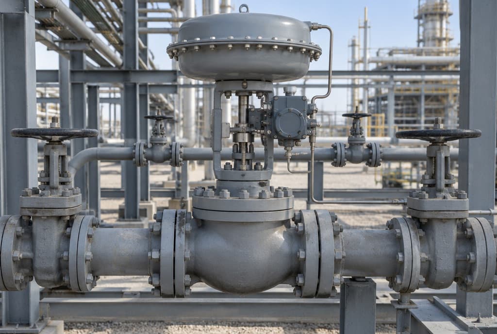
The single-port globe valve is the most common control valve body. Two things set its behaviour: how the plug is guided, and whether line pressure is balanced across it.
- Post-, stem- or top-guided, unbalanced plug. The plug is guided at the top and closes onto a single seat ring. Upstream pressure loads the whole port area, so the actuator has to overcome that unbalanced force as well as seat the plug. It suits smaller sizes and stringent shutoff, with metal or soft (PTFE-type) seats. The Emerson handbook warns that these plugs can be prone to vibration at high pressure drop. Our top-guided single-seated globe valve is this type, for general clean-fluid loops.
- Cage-guided, balanced plug. A cylindrical cage holds the seat ring, guides the plug along its stroke and sets the flow characteristic through the shape of its windows. Balance holes let downstream pressure act on both faces of the plug, which cancels most of the static force, so a smaller actuator can drive a larger valve or a higher drop. A seal between the plug and the cage bore limits leakage of upstream fluid past the plug. Changing the cage changes the characteristic or the capacity, or adds noise or cavitation reduction, without changing the body. See our cage-guided balanced valve.
- Double-ported. Two plugs on one stem, nearly balanced by flow. The industry has largely moved away from them: metal-seated double-port valves usually reach only Class II shutoff.
| Class | Maximum leakage | Test medium and pressure | Recommended seat load (Emerson) |
|---|---|---|---|
| II | 0.5% of rated capacity | Air or water, 3–4 bar (45–60 psig) or max. operating ∆P, whichever is lower | 20 lb per inch of port circumference |
| III | 0.1% of rated capacity | As Class II | 40 lb per inch of port circumference |
| IVHighlighted | 0.01% of rated capacity | As Class II | 40 lb/in up to a 4-3/8 in port; 80 lb/in above |
| V | 0.0005 ml/min of water per inch of port diameter per psi ∆P | Water at max. service ∆P, body cavity filled, net actuator thrust only | Metal seats: rises with shutoff pressure drop |
| VI | By port size, e.g. 0.15 ml/min (1 bubble/min) at 1 in, 6.75 ml/min (45/min) at 8 in | Air or nitrogen, 3.5 bar (50 psig) or max. rated ∆P, whichever is lower | Metal seats: 300 lb per inch of port circumference |
Class I means no test, by agreement. Ask for the class you need rather than “tight shutoff”: each step up needs more seat load, and so a larger actuator.
/02Rotary and angle valves.
V-notch segmental ball. Only part of a sphere is used, with a V-shaped notch at its leading edge. As the shaft turns, the notch opens progressively against the seal ring, giving an equal-percentage characteristic and wide rangeability; the handbook quotes better than 300:1 for one design. The ball stays in contact with the seal through its travel, so it shears fibres and solids as it closes instead of trapping them. That makes our V-notch ball control valve the usual choice for pulp, slurries, viscous and erosive fluids. Segmental ball valves mate with Class 150, 300 and 600 flanges, which matches the range we list.
Angle valves. An angle body turns the flow through 90° and can replace an elbow. It is the traditional answer to flashing and erosive duties because the flow path has few changes of direction and the throttled jet leaves into the outlet pipe rather than impinging on the body wall. Angle valves are used on boiler feedwater and heater drains, often with an expanded outlet to slow the flow, restricted trim, or an outlet liner. The plug and seat take the wear, so hard materials — hard facing, carbides or ceramics — are specified. Our erosion-resistant angle valve is built this way.
/03Cavitation, flashing and multi-stage trim.
As liquid passes the throttling point it speeds up and its pressure falls to a minimum at the vena contracta, just downstream of the restriction. Downstream the flow slows and pressure partly recovers. Streamlined valves such as ball valves recover a lot of pressure (high-recovery); globe valves recover less (low-recovery). If the vena contracta pressure falls below the liquid’s vapour pressure, vapour bubbles form. What happens next depends on the outlet pressure:
- Cavitation: outlet pressure recovers above vapour pressure and the bubbles collapse. It sounds like gravel in the line and leaves a rough, cinder-like surface on the trim, body or downstream pipe. High-recovery valves are more prone to it.
- Flashing: outlet pressure stays below vapour pressure, so the vapour stays in the stream. Damage is smooth and polished, worst at the seat line. Because outlet pressure is set by the plant, no control valve can prevent flashing; you choose geometry and materials to survive it. Flashing water in plain carbon steel combines corrosion with erosion, so low-alloy steel is the minimum.
Cavitation, unlike flashing, can be designed out. Multi-stage trim splits the total drop into several smaller drops in series, each small enough that its own vena contracta stays above vapour pressure, so bubbles never form. Our multi-stage pressure-reducing valve does this with stacked sleeves on a balanced plug, for duties such as boiler feed recirculation. The other options are to harden and isolate the surfaces the cavitation reaches, or to raise the outlet pressure. Small anti-cavitation passages can clog, so tell us about any solids in the fluid.
/04Bellows seals for fluids that must not leak.
Packing seals a moving stem well, but not perfectly. A bellows seal bonnet welds a metal bellows between the plug stem and the bonnet, so the process fluid never reaches the stem or the packing. The Emerson handbook places it where stem leakage below 1 × 10⁻⁶ cc/s of helium is required: toxic, volatile, radioactive or very expensive fluids. A conventional or low-emission packing box sits above the bellows as a back-up if the bellows fails. Bellows pressure ratings fall as temperature rises, and cycle life depends on the bellows material and type — welded-leaf bellows are shorter, mechanically formed bellows are taller and more repeatable — so give the stroke frequency with the enquiry. We list the single-seated bellows valve and a cage-guided bellows valve for larger balanced duties.
/05Sizing, characteristic and actuator.
Cv. The flow coefficient is the number of US gallons per minute of 60 °F water that passes with a 1 psi drop at a given travel. The sizing equations come from ANSI/ISA-75.01.01, which is harmonised with IEC 60534-2-1, so either may be used. They assume a single-phase Newtonian fluid with fully turbulent flow; slurries and high-viscosity fluids need extra care. For liquids, if the actual drop exceeds the choked drop (∆Pchoked), the choked figure is used — and that is the warning that the valve will cavitate or flash. Cv and the recovery factor FL are a matched set for one valve at one travel, which is why the sizing belongs to the valve supplier.
Inherent characteristics
- Equal percentage: each increment of travel changes flow by the same percentage of the existing flow. Used for pressure control and where most of the system drop is outside the valve, or the drop varies widely.
- Linear: flow is proportional to travel, for constant gain. Common on liquid level and some flow loops.
- Quick opening: most of the flow in the first part of travel; used mainly for on/off duty.
These are measured at constant drop. Installed, the drop changes with flow, so the installed characteristic is what the loop sees.
Actuators and positioners
The spring-and-diaphragm actuator is the most common: air pushes the diaphragm, the spring pushes back, and the spring sets the fail action — fail-closed or fail-open when air is lost. Piston actuators work on plant air up to about 150 psig for higher thrust and faster stroking, double-acting or spring-return. A positioner reads stem or shaft position and drives the actuator until it matches the control signal: 3–15 psig on pneumatic loops, 4–20 mA on most modern plants, often with HART diagnostics. Routine shop testing of control valves, including the pneumatic actuator, is covered by IEC 60534-4, which applies to ratings up to Class 2500.
Common questions
- What is the difference between a top-guided and a cage-guided control valve?
- A top-guided plug is unbalanced and seats on a single ring, good for small sizes and tight shutoff. A cage-guided plug is guided by a cage, usually balanced, so it needs less actuator force at high drop.
- Which leakage class should I specify?
- Class IV (0.01% of rated capacity) suits most metal-seated throttling duties. Ask for Class V for metal seats that must hold close to tight, and Class VI, tested by bubble count, only where the duty needs the tightest class: it needs the most seat load.
- Can a control valve stop flashing?
- No. Flashing happens because the outlet pressure is below the vapour pressure, which the plant sets. An angle body, expanded outlet and hardened trim limit the damage.
- How does anti-cavitation trim work?
- It takes the pressure drop in several stages, so no single stage drops the local pressure below vapour pressure. No bubbles form, so none collapse against the metal.
- When is a V-notch ball better than a globe valve?
- On slurries, pulp, fibrous or viscous fluids, and where high capacity and wide rangeability are needed at moderate pressure classes.
- What data do you need to size a control valve?
- Fluid, minimum, normal and maximum flow, inlet and outlet pressure at each, temperature, density, vapour and critical pressure, viscosity, line size and schedule, leakage class and fail action.
What we list
Control valves built to the data sheet, with actuator, positioner and accessories assembled and tested:
- Angle Control Valve, Erosion Resistant
- Bellows-Seal Cage-Guided Control Valve
- Bellows-Seal Single-Seated Control Valve
- Cage-Guided Control Valve, Pressure-Balanced Trim
- Multi-Stage Pressure-Reducing Control Valve, Anti-Cavitation
- Single-Seated Globe Control Valve, Top Guided
- V-Notch Segmental Ball Control Valve
For a quote, send the process data sheet or: fluid and phase, minimum/normal/maximum flow with P1 and P2 at each, temperature, vapour pressure, line size and schedule, pressure class and end connection, body and trim material, leakage class, fail action, signal (3–15 psig or 4–20 mA, HART) and any noise limit. For cryogenic duty, see the cryogenic globe control valve and our guide to cryogenic valves.
Control valves
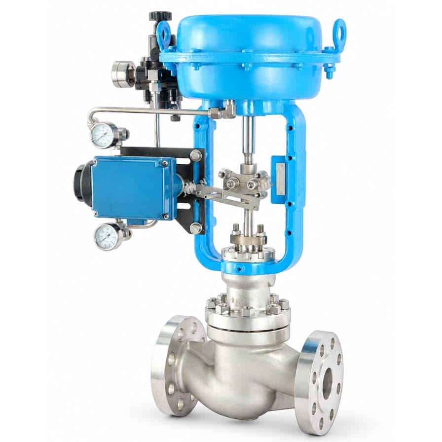 IH-PV-CVSSingle-Seated Globe Control Valve, Top GuidedIndus Hydraulics
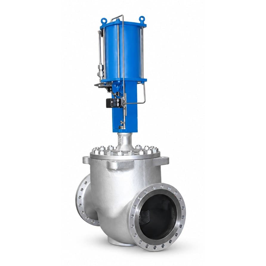 IH-PV-CVCCage-Guided Control Valve, Pressure-Balanced TrimIndus Hydraulics
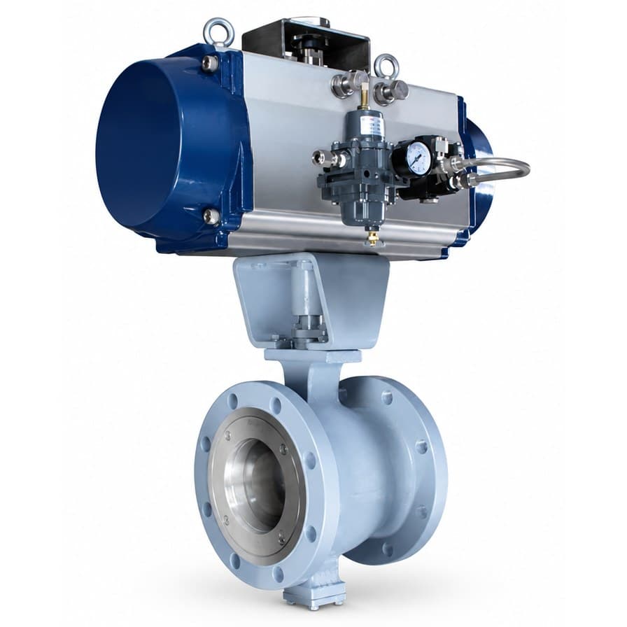 IH-PV-CVVV-Notch Segmental Ball Control ValveIndus Hydraulics
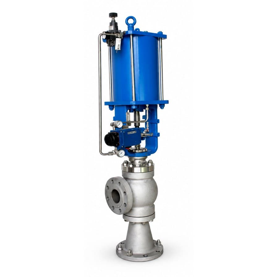 IH-PV-CVAAngle Control Valve, Erosion ResistantIndus Hydraulics
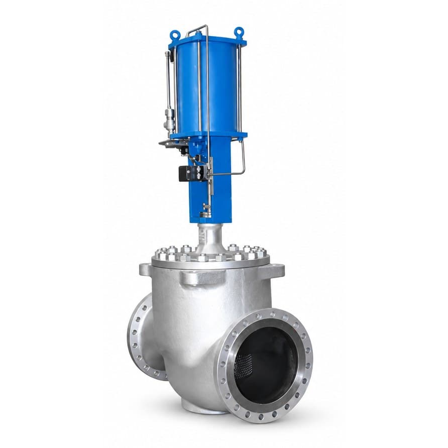 IH-PV-CVMMulti-Stage Pressure-Reducing Control Valve, Anti-CavitationIndus Hydraulics
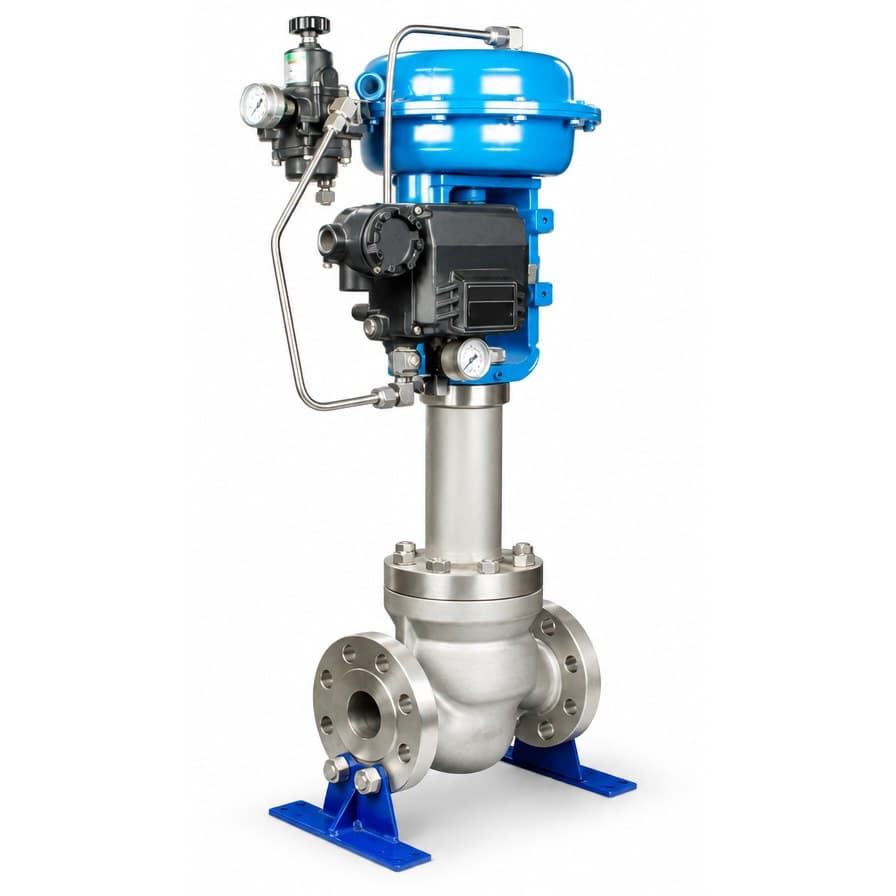 IH-PV-CVBBellows-Seal Single-Seated Control ValveIndus Hydraulics
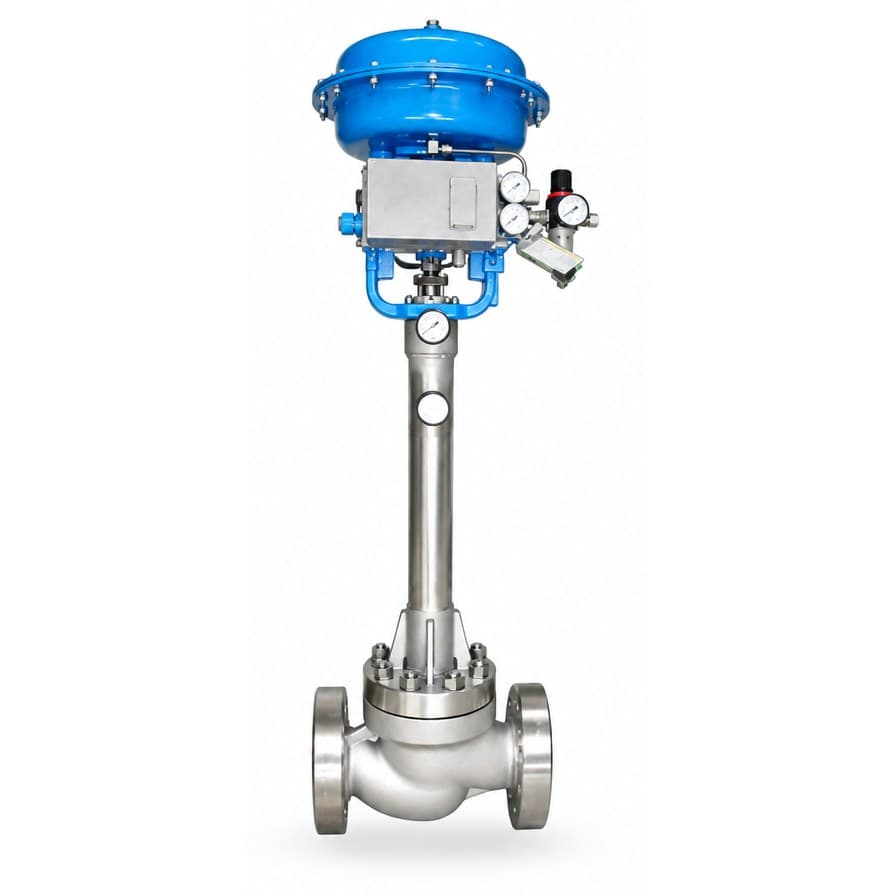 IH-PV-CVGBellows-Seal Cage-Guided Control ValveIndus Hydraulics