A cylinder sized correctly for force can still fail early — the piston hammering the end cover because the moving mass is too fast, or the rod bearing wearing oval because the mounting pushes it sideways. Both failures come from choices made after sizing: the cushioning, the mounting style and the connection to the load. This guide covers each, using the limits the makers publish.
/01Air cushions and bumpers.
Adjustable air cushions
Parker describes the mechanism on its P1F: a threaded needle screw adjusts into an orifice in the end plate. Screwing it further in lets less air escape in a given time, and the slowed exhaust builds back-pressure that slows the piston as it enters the end cushioning seal. The cushion absorbs the kinetic energy of the load at both ends of the stroke.
Setting it is finished on the machine. SMC ships its C96 cushions pre-adjusted but says to readjust them for the actual load and speed when the cylinder goes into service — clockwise to stiffen, anticlockwise to soften. SMC’s warnings are worth following exactly:
- Not fully closed. Run with the cushion valve shut and the piston may bounce, fail to complete its stroke, or damage the cushion seal from excess pressure.
- Not over-opened. Open it beyond the allowable number of turns and the screw can blow out of the cover when air is applied. SMC gives 4 turns for 32 and 40 mm, 4.5 for 50 and 63 mm and 5.5 for 80 and 100 mm on C96.
- Not switched off. SMC says to use the air cushion whenever the cylinder runs; otherwise, above the non-cushioned energy limit, the piston rod assembly or tie rods will be damaged.
Bumpers
A bumper is a resilient pad on the piston or in the cover that takes the impact directly. It needs no adjustment and quietens the end of stroke, but absorbs less energy than an air cushion — compare SMC’s with and without figures below. Parker offers bumper piston seals on its 4MA for additional noise reduction and smooth end-of-stroke deceleration, and separate 1/4 in thick bumpers at either or both ends — each of which costs 1/4 in of stroke, so a 6 in stroke cylinder with bumpers at both ends has an effective stroke of 5-1/2 in. SMC notes a slight bounce at the stroke end with a bumper cushion. Parker’s P1F combines both: adjustable pneumatic cushioning plus a mechanical cushion that reduces the noise of the piston striking the end covers.
Our 4MA listings name the piston option where the part numbers share it — look for “Bumper Seals” or “Lipseals and Magnetic Ring” in the title.
/02Kinetic energy: what the makers publish.
The load arriving at the end of stroke carries kinetic energy E = ½ m v² (joules, with m in kg and v in m/s). The cushion has to absorb it. Makers publish the limit in two forms:
- SMC gives a table of allowable kinetic energy in joules per bore, with and without the air cushion (below), and states that running above it can break the product and cause injury. Its selection guide says to go to a larger bore or add an external stopper when the value is exceeded.
- Parker gives a diagram of maximum permissible speed at the start of cushioning against moving mass, per bore. For P1F it is valid for horizontal movement at 6 bar with the mass guided externally. For P1D it assumes low load, equilibrium speed, a correctly set cushion screw and 6 bar at the cylinder port — and at high relative load (more than 1 bar pressure drop across the piston), Parker says to reduce the mass by a factor of 2.5 for a given speed, or the speed by 1.5 for a given mass.
Two traps in the arithmetic
- Use the speed entering the cushion, not the average. Parker: the piston speed at the start of cushioning is typically about 50% higher than the average speed, and it is this higher speed that determines the cylinder. A 300 mm stroke in 0.6 s averages 0.5 m/s but arrives at about 0.75 m/s.
- Count the cylinder’s own moving parts. Parker publishes the moving mass for cushioning calculations — for a 63 mm P1D, 0.50 kg plus 0.025 kg per 10 mm of stroke.
Worked check
A 63 mm cylinder with 300 mm stroke moves a 15 kg guided load horizontally. Moving mass = 15 + 0.50 + (30 × 0.025) = 16.25 kg. At 0.5 m/s average, the cushion sees about 0.75 m/s: E = ½ × 16.25 × 0.75² = 4.6 J. Against SMC’s C96 figures for 63 mm, that is inside both the 11.4 J air-cushion limit and the 6.0 J non-cushion limit. Double the average speed to 1.0 m/s and the cushion sees 1.5 m/s: E = ½ × 16.25 × 1.5² = 18.3 J — beyond the air cushion. The options then are SMC’s: a speed-reduction circuit so the cylinder slows before the cushion, an external shock absorber, or a larger bore.
Parker’s diagrams are drawn for horizontal motion. A load travelling downwards is also pulled into the cushion by gravity; ask the maker for the vertical case rather than reading it off a horizontal chart.
| Bore (mm) | With air cushion (J) | Without air cushion (J) |
|---|---|---|
| 32 | 2.3 | 1.1 |
| 40 | 3.6 | 1.8 |
| 50 | 6.1 | 3.6 |
| 63Highlighted | 11.4 | 6.0 |
| 80 | 21.1 | 12.0 |
| 100 | 31.7 | 12.0 |
/03Mounting styles and the side load they cause.
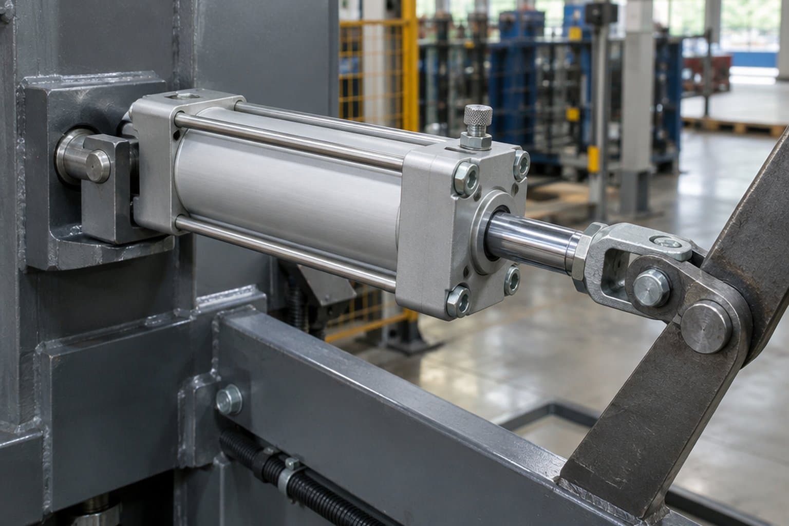
Mountings fall into two families. Fixed mountings — flanges, feet, side lugs, tapped ends, extended tie rods — hold the cylinder rigidly on one line. Pivot mountings — clevises, eyes and trunnions — let the cylinder swing, so it can follow a load that moves in an arc. Both are standardised: Parker’s 4MA catalogue lists 20 styles with their NFPA codes, and its P1F accessory range carries the ISO designations.
A cylinder’s rod bearing guides the rod; it is not designed to carry the load. SMC is direct: do not apply excessive lateral load to the piston rod, and it publishes allowable lateral load against stroke for C96. Parker is equally direct for P1D: where there are significant lateral loads on the piston rod, an external guide must be used to achieve maximum service life. Where Parker does offer side-load capacity, it names it: the 4MA can be ordered with a HI LOAD gland for side-load conditions.
How mountings create side load
- A fixed cylinder driving a guided load must be on exactly the same line as the guides. Any misalignment is forced through the rod bearing. SMC gives a field check: the cylinder should move the load smoothly at its own minimum operating pressure plus load weight × guide friction coefficient ÷ piston area. If it does, the guides are not loading the cylinder.
- A fixed cylinder pushing an unguided load carries the whole load on its rod. Use a guided cylinder or external guide instead.
- One-end (cantilever) mounting at speed. SMC warns that a cylinder fixed at one end only — a basic, flange or direct mount — can vibrate at the stroke end at high speed, and the bending moment damages it. Add a support bracket, or slow it down; long-stroke cylinders mounted horizontally from one end need the bracket anyway.
- Two cylinders on one load. SMC advises against moving a single load with synchronised cylinders: even if set to the same speed, their speeds drift apart and the load racks between them.
Protecting the rod
Dust on the rod is carried into the seal on every stroke. SMC says not to use its C96 in dusty locations or where water or oil splash it. Where the rod gets coated — Parker lists resin, ice, cement and sugar — Parker offers a metallic scraper on P1F and a metallic rod wiper on 4MA. On a dusty site, specify the scraper or wiper option when you order.
| Family | NFPA codes (Parker 4MA) | ISO accessories (Parker P1F) | Load path | Watch for |
|---|---|---|---|---|
| Flange | MF1 head, MF2 cap rectangular flange | MF1 / MF2 flange | Thrust on the cylinder axis | Alignment with the load; cantilever vibration at speed (SMC) |
| Foot / side | MS1 side end angles, MS2 side lugs, MS4 side tap, MS7 side end lugs | MS1 foot brackets | Thrust offset from the axis into the base | Alignment; rigid base (SMC) |
| Tie-rod extension / no mount | MX0–MX5 | — | As flange, on the tie rods | Alignment |
| Clevis / eye (pivot)Highlighted | MP1 cap fixed clevis, MP2 cap detachable clevis, MP4 cap detachable eye | MP2, MP4, MP6, AB6 brackets; CS7 swivel bearing | Swings with an arcing load | Buckling on long strokes; rod end must pivot too |
| Trunnion (pivot) | MT1 head, MT2 cap, MT4 intermediate | MT4 centre trunnion with AT4 brackets; MT5/MT6 flange trunnion | Swings about the trunnion pins | Buckling; pin wear — Parker MT4 can be positioned on the body |
/04Rod-end alignment couplers.
Even a well-aligned fixed cylinder is rarely perfectly in line with its load over the full stroke. A rigid rod-end connection turns every fraction of a degree into side load on the rod bearing. A self-aligning coupler between the rod and the load takes that out.
- Parker flexo coupling (PM5), for P1D and P1F, is intended to take up axial angle errors within ±4°. Parker uses the same flexo coupling to join its P1D rod-guidance modules to the piston rod, stating that it prevents the build-up of stresses in the cylinder.
- Swivel rod eye (AP6) with a DIN 648K spherical bearing, paired with an AB6 clevis bracket, for pivot-mounted cylinders whose rod end must also articulate.
- Rod clevis (AP2) for a pinned rod end.
Rule of thumb from the makers’ own designs: if the cylinder body is fixed and the load is guided, couple the rod to the load through a flexible coupling; if the cylinder pivots, the rod end must pivot in the same plane.
/05Buckling and stroke limits.
A long, thin rod pushing a load is a column, and a column buckles. SMC’s approach is the simplest to apply: assuming the force the cylinder generates acts as a buckling force on the rod, it tabulates the maximum usable stroke for each bore at 0.3, 0.5 and 0.7 MPa, for foot, rod-flange, head-flange, clevis and trunnion mountings. SMC stresses the stroke limit applies regardless of the load factor: even under a light load, once the rod is stopped by an external stopper at the extending end, the cylinder’s full force acts on it.
So check buckling for any long-stroke cylinder that pushes, and above all for clamps and presses that stall on the workpiece. The limit moves with three things you control: the bore and rod (a bigger rod is stiffer), the pressure (less force, longer allowable stroke), and the mounting style, which sets how the column is supported at each end.
The fixes Parker offers on 4MA
- Oversize rods. The 4MA order code includes oversize rod numbers 2 and 3, and Parker refers you to its piston-rod selection chart to choose the rod diameter. Our 4MA listings for “Rod Number 2” and “Rod Number 3” are those.
- Stop tubes. Parker lets you add a stop tube by ordering the gross stroke (net stroke plus stop tube) and specifying the tube length in the order notes. Whether a stroke needs one comes from Parker’s rod selection chart — send us the stroke, bore, pressure and mounting and we will check it.
- HI LOAD gland where the rod also sees side load.
For ISO cylinders, use the maker’s buckling or rod-load data for the series, and do not extrapolate one maker’s table to another’s cylinder: the standard fixes the mounting dimensions, not the rod material or bearing length.
Cushioning and mounting checks
IfIs ½mv² at cushion-entry speed (about 1.5× average) inside the maker’s limit?
Yes: set the air cushion on commissioning. No: slow the cylinder before the cushion, add a shock absorber or go up a bore.
IfLight load, low speed, noise the main concern?
Bumpers are enough — allow for the stroke they take up (1/4 in per bumper on Parker 4MA).
IfLoad guided separately from the cylinder?
Fixed mounting, with a flexo coupling at the rod end (±4° on Parker PM5).
IfLoad moves in an arc?
Clevis or trunnion mounting with a swivel rod eye or clevis at the rod end.
IfLoad pushes sideways on the rod?
Guided cylinder or external guide; Parker 4MA HI LOAD gland for moderate side load.
IfLong stroke pushing, or a clamp that stalls on the work?
Check the maker’s buckling stroke limit; consider an oversize rod or a stop tube.
Common questions
- How does a pneumatic cylinder air cushion work?
- Near the end of stroke the main exhaust is cut off and the remaining air escapes through an orifice set by a needle screw. The back-pressure this builds slows the piston before it reaches the end cover.
- How do I adjust the cushion on an air cylinder?
- Set it on the machine with the real load and speed. Turn the screw in to stiffen, out to soften. SMC warns not to run it fully closed (the piston may bounce or not complete the stroke) and not to open it past the allowable turns.
- What is the difference between an air cushion and a bumper?
- An air cushion is adjustable and absorbs more energy — on SMC’s C96, roughly twice the non-cushioned figure. A bumper is a fixed pad that needs no adjustment and absorbs less energy; Parker’s separate 4MA bumpers take up 1/4 in of stroke each.
- How do I calculate kinetic energy for a pneumatic cylinder?
- E = ½ × moving mass × speed², with the mass including the piston and rod and the speed taken at the start of cushioning. Parker says that speed is typically about 50% above the average speed.
- Can a pneumatic cylinder take side load?
- Not much. SMC warns against excessive lateral load on the rod and Parker requires an external guide under significant lateral load on P1D. Use a guided cylinder, an external guide, or a flexible rod coupling to remove misalignment.
- What limits the stroke of a pneumatic cylinder?
- Rod buckling. SMC tabulates the maximum stroke by bore, pressure and mounting style, independent of the load. Parker offers oversize rods and stop tubes on 4MA for long strokes.
/06What we list.
Every cylinder on our shelf is linked below — Parker 4MA (including bumper-seal and oversize-rod listings) and 2MNR tie-rod, P1D and P1F ISO 15552, SR-family round body, LP compact and HB/P5E guided cylinders, plus Destaco. Tell us the mounting and rod end with the part number and we will quote the cylinder and its accessories.
Parker 4MA NFPA tie-rod cylinders
28 listings.
- Parker 4MA Series Tie Rod Pneumatic Cylinders, 1 1/2" Bore
- Parker 4MA Series Tie Rod Pneumatic Cylinders, 1 Inch Bore
- Parker 4MA Series Tie Rod Pneumatic Cylinders, 1 Inch Bore, Full Male
- Parker 4MA Series Tie Rod Pneumatic Cylinders, 1 Inch Bore, Intermediate Male, Rod Number 2
- Parker 4MA Series Tie Rod Pneumatic Cylinders, 1 Inch Bore, Intermediate Male, Rod Number 3
- Parker 4MA Series Tie Rod Pneumatic Cylinders, 1 Inch Bore, Lip Seal Piston
- Parker 4MA Series Tie Rod Pneumatic Cylinders, 1 Inch Bore, Short Female, Rod Number 3
- Parker 4MA Series Tie Rod Pneumatic Cylinders, 1 Inch Bore, Small Male
- Parker 4MA Series Tie Rod Pneumatic Cylinders, 1-1/2 Inch Bore, Lipseals And Magnetic Ring
- Parker 4MA Series Tie Rod Pneumatic Cylinders, 2 Inch Bore
- Parker 4MA Series Tie Rod Pneumatic Cylinders, 2 Inch Bore, LipSeals And Magnetic Ring
- Parker 4MA Series Tie Rod Pneumatic Cylinders, 2-1/2 Inch Bore
- Parker 4MA Series Tie Rod Pneumatic Cylinders, 3-1/4 Inch Bore
- Parker 4MA Series Tie Rod Pneumatic Cylinders, 4 Inch Bore, Bumper Seals
- Parker 4MA Series Tie Rod Pneumatic Cylinders, 4 Inch Bore, Lipseals And Magnetic Ring, SAE Ports
- Parker 4MA Series Tie Rod Pneumatic Cylinders, 4" Bore
- Parker 4MA Series Tie Rod Pneumatic Cylinders, 5 Inch Bore
- Parker 4MA Series Tie Rod Pneumatic Cylinders, 6" Bore
- Parker 4MA Series Tie Rod Pneumatic Cylinders, 8" Bore
- Parker 4MA Series Tie Rod Pneumatic Cylinders, Aluminum Piston, 3 1/4" Bore
- Parker 4MA Series Tie Rod Pneumatic Cylinders, Lipseals And Magnetic Ring, 2 1/2" Bore
- Parker 4MA Series Tie Rod Pneumatic Cylinders, Lipseals And Magnetic Ring, 3 1/4" Bore
- Parker 4MA Series Tie Rod Pneumatic Cylinders, Lipseals And Magnetic Ring, NPTF Port, 4" Bore
- Parker 4MA Series Tie Rod Pneumatic Cylinders, Lipseals, 1 1/2" Bore
- Parker 4MA Series Tie Rod Pneumatic Cylinders, Lipseals, 2 1/2" Bore
- Parker 4MA Series Tie Rod Pneumatic Cylinders, Lipseals, 2" Bore
- Parker 4MA Series Tie Rod Pneumatic Cylinders, Lipseals, 3 1/4" Bore
- Parker 4MA Series Tie Rod Pneumatic Cylinders, Lipseals, 4" Bore
Parker 4MA NFPA tie-rod cylinders, 1P part numbers
80 listings.
- Parker 4MA Series Tie Rod Pneumatic Cylinders, 1 1/2" Bore, 1P Part Numbers
- Parker 4MA Series Tie Rod Pneumatic Cylinders, 2 1/2" Bore, 1P Part Numbers
- Parker 4MA Series Tie Rod Pneumatic Cylinders, 2" Bore, 1P Part Numbers
- Parker 4MA Series Tie Rod Pneumatic Cylinders, 3 1/4" Bore, 1P Part Numbers
- Parker 4MA Series Tie Rod Pneumatic Cylinders, 4" Bore, 1P Part Numbers
- Parker 4MA Series Tie Rod Pneumatic Cylinders, 5" Bore, 1P Part Numbers
- Parker 4MA Series Tie Rod Pneumatic Cylinders, 6" Bore, 1P Part Numbers
- Parker 4MA Series Tie Rod Pneumatic Cylinders, 8" Bore, 1P Part Numbers
- Parker 4MA Series Tie Rod Pneumatic Cylinders, Full Male, 1 1/2" Bore, 1P Part Numbers
- Parker 4MA Series Tie Rod Pneumatic Cylinders, Full Male, 2 1/2" Bore, 1P Part Numbers
- Parker 4MA Series Tie Rod Pneumatic Cylinders, Full Male, 2" Bore, 1P Part Numbers
- Parker 4MA Series Tie Rod Pneumatic Cylinders, Full Male, 3 1/4" Bore, 1P Part Numbers
- Parker 4MA Series Tie Rod Pneumatic Cylinders, Full Male, 4" Bore, 1P Part Numbers
- Parker 4MA Series Tie Rod Pneumatic Cylinders, Full Male, 5" Bore, 1P Part Numbers
- Parker 4MA Series Tie Rod Pneumatic Cylinders, Full Male, 6" Bore, 1P Part Numbers
- Parker 4MA Series Tie Rod Pneumatic Cylinders, Full Male, 8" Bore, 1P Part Numbers
- Parker 4MA Series Tie Rod Pneumatic Cylinders, Intermediate Male, Rod Number 1, 1 1/2" Bore, 1P Part Numbers
- Parker 4MA Series Tie Rod Pneumatic Cylinders, Intermediate Male, Rod Number 1, 2 1/2" Bore, 1P Part Numbers
- Parker 4MA Series Tie Rod Pneumatic Cylinders, Intermediate Male, Rod Number 1, 2" Bore, 1P Part Numbers
- Parker 4MA Series Tie Rod Pneumatic Cylinders, Intermediate Male, Rod Number 1, 3 1/4" Bore, 1P Part Numbers
- Parker 4MA Series Tie Rod Pneumatic Cylinders, Intermediate Male, Rod Number 1, 4" Bore, 1P Part Numbers
- Parker 4MA Series Tie Rod Pneumatic Cylinders, Intermediate Male, Rod Number 1, 5" Bore, 1P Part Numbers
- Parker 4MA Series Tie Rod Pneumatic Cylinders, Intermediate Male, Rod Number 1, 6" Bore, 1P Part Numbers
- Parker 4MA Series Tie Rod Pneumatic Cylinders, Intermediate Male, Rod Number 1, 8" Bore, 1P Part Numbers
- Parker 4MA Series Tie Rod Pneumatic Cylinders, Intermediate Male, Rod Number 2, 1 1/2" Bore, 1P Part Numbers
- Parker 4MA Series Tie Rod Pneumatic Cylinders, Intermediate Male, Rod Number 2, 2 1/2" Bore, 1P Part Numbers
- Parker 4MA Series Tie Rod Pneumatic Cylinders, Intermediate Male, Rod Number 2, 2" Bore, 1P Part Numbers
- Parker 4MA Series Tie Rod Pneumatic Cylinders, Intermediate Male, Rod Number 2, 3 1/4" Bore, 1P Part Numbers
- Parker 4MA Series Tie Rod Pneumatic Cylinders, Intermediate Male, Rod Number 2, 4" Bore, 1P Part Numbers
- Parker 4MA Series Tie Rod Pneumatic Cylinders, Intermediate Male, Rod Number 2, 5" Bore, 1P Part Numbers
- Parker 4MA Series Tie Rod Pneumatic Cylinders, Intermediate Male, Rod Number 2, 6" Bore, 1P Part Numbers
- Parker 4MA Series Tie Rod Pneumatic Cylinders, Intermediate Male, Rod Number 2, 8" Bore, 1P Part Numbers
- Parker 4MA Series Tie Rod Pneumatic Cylinders, Intermediate Male, Rod Number 3, 1 1/2" Bore, 1P Part Numbers
- Parker 4MA Series Tie Rod Pneumatic Cylinders, Intermediate Male, Rod Number 3, 2 1/2" Bore, 1P Part Numbers
- Parker 4MA Series Tie Rod Pneumatic Cylinders, Intermediate Male, Rod Number 3, 2" Bore, 1P Part Numbers
- Parker 4MA Series Tie Rod Pneumatic Cylinders, Intermediate Male, Rod Number 3, 3 1/4" Bore, 1P Part Numbers
- Parker 4MA Series Tie Rod Pneumatic Cylinders, Intermediate Male, Rod Number 3, 4" Bore, 1P Part Numbers
- Parker 4MA Series Tie Rod Pneumatic Cylinders, Intermediate Male, Rod Number 3, 5" Bore, 1P Part Numbers
- Parker 4MA Series Tie Rod Pneumatic Cylinders, Intermediate Male, Rod Number 3, 6" Bore, 1P Part Numbers
- Parker 4MA Series Tie Rod Pneumatic Cylinders, Intermediate Male, Rod Number 3, 8" Bore, 1P Part Numbers
- Parker 4MA Series Tie Rod Pneumatic Cylinders, Lip Seal Piston, 1 1/2" Bore, 1P Part Numbers
- Parker 4MA Series Tie Rod Pneumatic Cylinders, Lip Seal Piston, 2 1/2" Bore, 1P Part Numbers
- Parker 4MA Series Tie Rod Pneumatic Cylinders, Lip Seal Piston, 2" Bore, 1P Part Numbers
- Parker 4MA Series Tie Rod Pneumatic Cylinders, Lip Seal Piston, 3 1/4" Bore, 1P Part Numbers
- Parker 4MA Series Tie Rod Pneumatic Cylinders, Lip Seal Piston, 4" Bore, 1P Part Numbers
- Parker 4MA Series Tie Rod Pneumatic Cylinders, Lip Seal Piston, 5" Bore, 1P Part Numbers
- Parker 4MA Series Tie Rod Pneumatic Cylinders, Lip Seal Piston, 6" Bore, 1P Part Numbers
- Parker 4MA Series Tie Rod Pneumatic Cylinders, Lip Seal Piston, 8" Bore, 1P Part Numbers
- Parker 4MA Series Tie Rod Pneumatic Cylinders, Short Female, Rod Number 1, 1 1/2" Bore, 1P Part Numbers
- Parker 4MA Series Tie Rod Pneumatic Cylinders, Short Female, Rod Number 1, 2 1/2" Bore, 1P Part Numbers
- Parker 4MA Series Tie Rod Pneumatic Cylinders, Short Female, Rod Number 1, 2" Bore, 1P Part Numbers
- Parker 4MA Series Tie Rod Pneumatic Cylinders, Short Female, Rod Number 1, 3 1/4" Bore, 1P Part Numbers
- Parker 4MA Series Tie Rod Pneumatic Cylinders, Short Female, Rod Number 1, 4" Bore, 1P Part Numbers
- Parker 4MA Series Tie Rod Pneumatic Cylinders, Short Female, Rod Number 1, 5" Bore, 1P Part Numbers
- Parker 4MA Series Tie Rod Pneumatic Cylinders, Short Female, Rod Number 1, 6" Bore, 1P Part Numbers
- Parker 4MA Series Tie Rod Pneumatic Cylinders, Short Female, Rod Number 1, 8" Bore, 1P Part Numbers
- Parker 4MA Series Tie Rod Pneumatic Cylinders, Short Female, Rod Number 2, 1 1/2" Bore, 1P Part Numbers
- Parker 4MA Series Tie Rod Pneumatic Cylinders, Short Female, Rod Number 2, 2 1/2" Bore, 1P Part Numbers
- Parker 4MA Series Tie Rod Pneumatic Cylinders, Short Female, Rod Number 2, 2" Bore, 1P Part Numbers
- Parker 4MA Series Tie Rod Pneumatic Cylinders, Short Female, Rod Number 2, 3 1/4" Bore, 1P Part Numbers
- Parker 4MA Series Tie Rod Pneumatic Cylinders, Short Female, Rod Number 2, 4" Bore, 1P Part Numbers
- Parker 4MA Series Tie Rod Pneumatic Cylinders, Short Female, Rod Number 2, 5" Bore, 1P Part Numbers
- Parker 4MA Series Tie Rod Pneumatic Cylinders, Short Female, Rod Number 2, 6" Bore, 1P Part Numbers
- Parker 4MA Series Tie Rod Pneumatic Cylinders, Short Female, Rod Number 2, 8" Bore, 1P Part Numbers
- Parker 4MA Series Tie Rod Pneumatic Cylinders, Short Female, Rod Number 3, 1 1/2" Bore, 1P Part Numbers
- Parker 4MA Series Tie Rod Pneumatic Cylinders, Short Female, Rod Number 3, 2 1/2" Bore, 1P Part Numbers
- Parker 4MA Series Tie Rod Pneumatic Cylinders, Short Female, Rod Number 3, 2" Bore, 1P Part Numbers
Parker 4MA NFPA tie-rod cylinders, 1P part numbers (continued)
- Parker 4MA Series Tie Rod Pneumatic Cylinders, Short Female, Rod Number 3, 3 1/4" Bore, 1P Part Numbers
- Parker 4MA Series Tie Rod Pneumatic Cylinders, Short Female, Rod Number 3, 4" Bore, 1P Part Numbers
- Parker 4MA Series Tie Rod Pneumatic Cylinders, Short Female, Rod Number 3, 5" Bore, 1P Part Numbers
- Parker 4MA Series Tie Rod Pneumatic Cylinders, Short Female, Rod Number 3, 6" Bore, 1P Part Numbers
- Parker 4MA Series Tie Rod Pneumatic Cylinders, Short Female, Rod Number 3, 8" Bore, 1P Part Numbers
- Parker 4MA Series Tie Rod Pneumatic Cylinders, Small Male, 1 1/2" Bore, 1P Part Numbers
- Parker 4MA Series Tie Rod Pneumatic Cylinders, Small Male, 2 1/2" Bore, 1P Part Numbers
- Parker 4MA Series Tie Rod Pneumatic Cylinders, Small Male, 2" Bore, 1P Part Numbers
- Parker 4MA Series Tie Rod Pneumatic Cylinders, Small Male, 3 1/4" Bore, 1P Part Numbers
- Parker 4MA Series Tie Rod Pneumatic Cylinders, Small Male, 4" Bore, 1P Part Numbers
- Parker 4MA Series Tie Rod Pneumatic Cylinders, Small Male, 5" Bore, 1P Part Numbers
- Parker 4MA Series Tie Rod Pneumatic Cylinders, Small Male, 6" Bore, 1P Part Numbers
- Parker 4MA Series Tie Rod Pneumatic Cylinders, Small Male, 8" Bore, 1P Part Numbers
Parker 2MNR non-rotating tie-rod cylinders
5 listings.
- Parker 2MNR Series Tie Rod Pneumatic Cylinders, 1-1/2 Inch Bore
- Parker 2MNR Series Tie Rod Pneumatic Cylinders, 2 Inch Bore
- Parker 2MNR Series Tie Rod Pneumatic Cylinders, 2-1/2 Inch Bore
- Parker 2MNR Series Tie Rod Pneumatic Cylinders, 3-1/4 Inch Bore
- Parker 2MNR Series Tie Rod Pneumatic Cylinders, 4 Inch Bore
Parker P1D and P1F ISO 15552 cylinders
16 listings.
- Parker P1D Series Tie Rod Pneumatic Cylinders, Aluminum Piston, BSPP Ports, Male Rod End, 80 mm Bore
- Parker P1D Series Tie Rod Pneumatic Cylinders, Composite Piston, BSPP Ports, Male Rod End, 63 mm Bore
- Parker P1D Series Tie Rod Pneumatic Cylinders, Composite Piston, NPTF Ports, Female Rod End
- Parker P1F Series Tie Rod Pneumatic Cylinders, Smooth Profile With Dynamic Rod Lock, 100mm Bore
- Parker P1F Series Tie Rod Pneumatic Cylinders, Smooth Profile With Through Rod, 32mm Bore
- Parker P1F Series Tie Rod Pneumatic Cylinders, Smooth Profile With Through Rod, 40mm Bore
- Parker P1F Series Tie Rod Pneumatic Cylinders, Smooth Profile With Through Rod, 63mm Bore
- Parker P1F Series Tie Rod Pneumatic Cylinders, Smooth Profile, 100mm Bore
- Parker P1F Series Tie Rod Pneumatic Cylinders, Smooth Profile, 32mm Bore
- Parker P1F Series Tie Rod Pneumatic Cylinders, Smooth Profile, 40mm Bore
- Parker P1F Series Tie Rod Pneumatic Cylinders, Smooth Profile, 50mm Bore
- Parker P1F Series Tie Rod Pneumatic Cylinders, Smooth Profile, 63mm Bore
- Parker P1F Series Tie Rod Pneumatic Cylinders, Smooth Profile, 80mm Bore
- Parker P1F Series Tie Rod Pneumatic Cylinders, Tie-Rod, 160mm Bore
- Parker P1F Series Tie Rod Pneumatic Cylinders, Tie-Rod, 250mm Bore
- Parker P1F Series Tie Rod Pneumatic Cylinders, Tie-Rod, 320mm Bore
Parker round-body cylinders: SR family, S Series and P1A
57 listings.
- Parker P1A Series Round Body Pneumatic Cylinders
- Parker S Series Air Cylinders, Nose Mounted
- Parker S Series Air Cylinders, Universal Mounting
- Parker SR Series Air Cylinders, 1 1/16" Bore
- Parker SR Series Air Cylinders, 1 1/16" Bore, 1P Part Numbers
- Parker SR Series Air Cylinders, 1 1/2" Bore, 1P Part Numbers
- Parker SR Series Air Cylinders, 1 1/4" Bore, 1P Part Numbers
- Parker SR Series Air Cylinders, 1 3/4" Bore, 1P Part Numbers
- Parker SR Series Air Cylinders, 1-1/16 Inch Bore
- Parker SR Series Air Cylinders, 1-1/2 Inch Bore
- Parker SR Series Air Cylinders, 1-1/4 Inch Bore
- Parker SR Series Air Cylinders, 1-3/4 Inch Bore
- Parker SR Series Air Cylinders, 1-Inch Bore
- Parker SR Series Air Cylinders, 1.062" Bore
- Parker SR Series Air Cylinders, 2 1/2" Bore, 1P Part Numbers
- Parker SR Series Air Cylinders, 2-1/2 Inch Bore
- Parker SR Series Air Cylinders, 2-Inch Bore
- Parker SR Series Air Cylinders, 2" Bore, 1P Part Numbers
- Parker SR Series Air Cylinders, 3-Inch Bore
- Parker SR Series Air Cylinders, 3" Bore, 1P Part Numbers
- Parker SR Series Air Cylinders, 3/4 Inch Bore
- Parker SR Series Air Cylinders, 3/4" Bore, 1P Part Numbers
- Parker SR Series Air Cylinders, 5/16 Inch Bore
- Parker SR Series Air Cylinders, 5/16" Bore, 1P Part Numbers
- Parker SR Series Air Cylinders, 7/16 Inch Bore
- Parker SR Series Air Cylinders, 7/16" Bore, 1P Part Numbers
- Parker SR Series Air Cylinders, 7/8 Inch Bore
- Parker SR Series Air Cylinders, 7/8" Bore, 1P Part Numbers
- Parker SR Series Air Cylinders, 9/16 Inch Bore
- Parker SR Series Air Cylinders, 9/16" Bore, 1P Part Numbers
- Parker SRD Series Air Cylinders, 1-1/16 Inch Bore
- Parker SRD Series Air Cylinders, 1-1/2 Inch Bore
- Parker SRD Series Air Cylinders, 2-Inch Bore
- Parker SRD Series Air Cylinders, 3/4 Inch Bore
- Parker SRD Series Air Cylinders, 9/16 Inch Bore
- Parker SRDM Series Round Body Pneumatic Cylinders
- Parker SRG Series Air Cylinders, 1-1/16 Inch Bore
- Parker SRG Series Air Cylinders, 1-1/2 Inch Bore
- Parker SRG Series Air Cylinders, 2-1/2 Inch Bore
- Parker SRG Series Air Cylinders, 2-Inch Bore
- Parker SRG Series Air Cylinders, 3/4 Inch Bore
- Parker SRGM Series Air Cylinders, 1-1/16 Inch Bore
- Parker SRGM Series Air Cylinders, 1-1/2 Inch Bore
- Parker SRGM Series Air Cylinders, 2-1/2 Inch Bore
- Parker SRGM Series Air Cylinders, 2-Inch Bore
- Parker SRGM Series Air Cylinders, 3/4 Inch Bore
- Parker SRM Series Air Cylinders, 1 1/16" Bore
- Parker SRM Series Air Cylinders, 1-1/16 Inch Bore
- Parker SRM Series Air Cylinders, 1-1/2 Inch Bore
- Parker SRM Series Air Cylinders, 1-1/4 Inch Bore
- Parker SRM Series Air Cylinders, 1-3/4 Inch Bore
- Parker SRM Series Air Cylinders, 1.062" Bore
- Parker SRM Series Air Cylinders, 2-1/2 Inch Bore
- Parker SRM Series Air Cylinders, 2-Inch Bore
- Parker SRM Series Air Cylinders, 3-Inch Bore
- Parker SRM Series Air Cylinders, 3/4 Inch Bore
- Parker SRM Series Air Cylinders, 9/16 Inch Bore
Parker compact and guided cylinders: LP, LPM, HB and P5E
16 listings.
- Parker HB Series Guided Pneumatic Cylinders, Compact Slide
- Parker LP Series Compact Pneumatic Cylinders, 1 Inch Bore
- Parker LP Series Compact Pneumatic Cylinders, 1-1/2 Inch bore
- Parker LP Series Compact Pneumatic Cylinders, 1-1/8 Inch Bore
- Parker LP Series Compact Pneumatic Cylinders, 2 Inch Bore
- Parker LP Series Compact Pneumatic Cylinders, 2-1/2 Inch Bore
- Parker LP Series Compact Pneumatic Cylinders, 3 Inch Bore
- Parker LP Series Compact Pneumatic Cylinders, 4 Inch Bore
- Parker LPM Series Compact Pneumatic Cylinders, 1 Inch Bore
- Parker LPM Series Compact Pneumatic Cylinders, 1-1/2 Inch Bore
- Parker LPM Series Compact Pneumatic Cylinders, 1-1/8 Inch Bore
- Parker LPM Series Compact Pneumatic Cylinders, 2 Inch Bore
- Parker LPM Series Compact Pneumatic Cylinders, 2-1/2 Inch Bore
- Parker LPM Series Compact Pneumatic Cylinders, 3 Inch Bore
- Parker LPM Series Compact Pneumatic Cylinders, 4 Inch Bore
- Parker P5E Series Guided Pneumatic Cylinders, Composite Bearing, Chrome Plated Oversize Shaft
Destaco cylinders
4 listings.
Cushioned, bumpered and guided cylinders
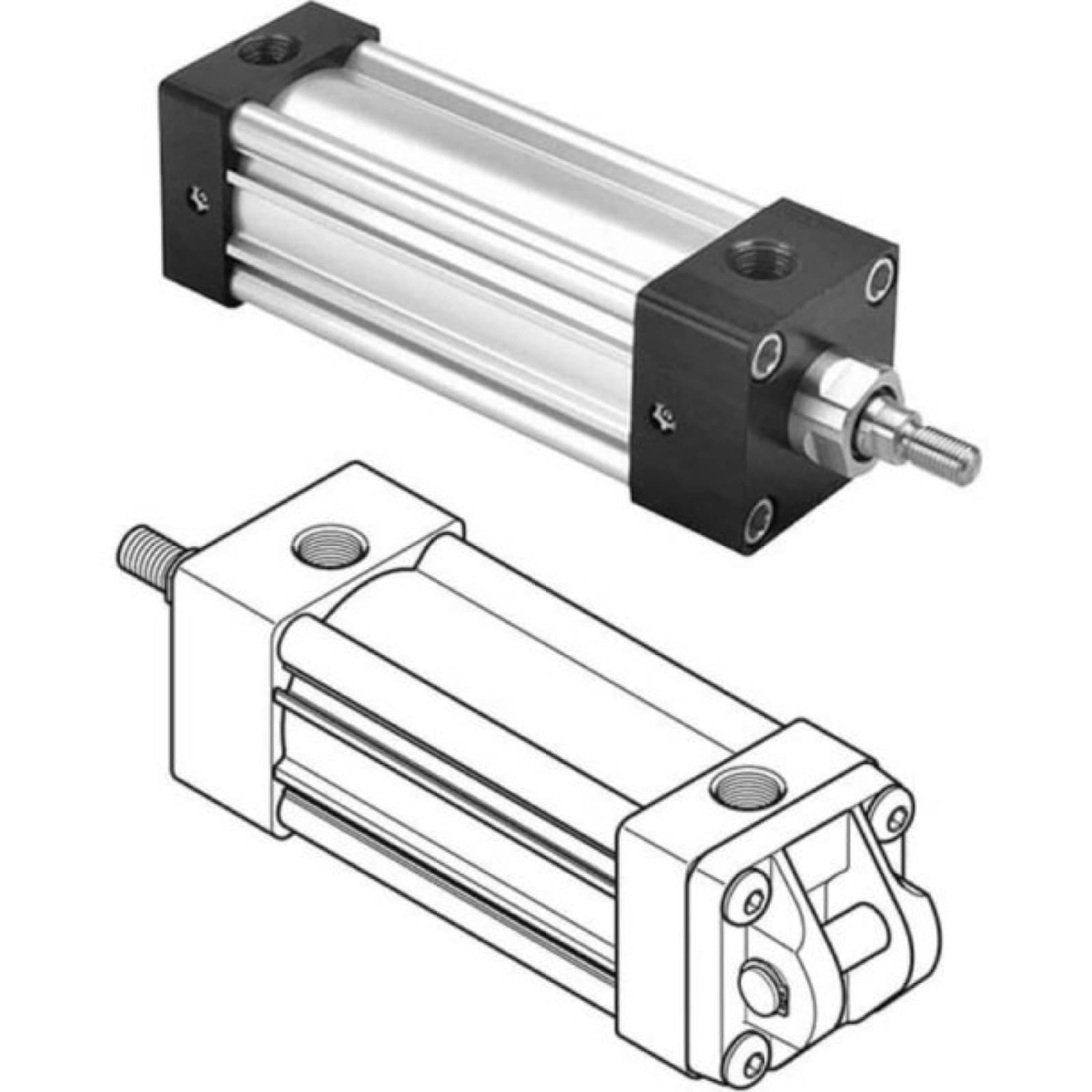 IH-PAR-4MA-SERIES-TIE-ROD-PNEUMATIC-CYLINDERS-4-INCH-3Parker 4MA Series Tie Rod Pneumatic Cylinders, 4 Inch Bore, Bumper SealsParker Hannifin
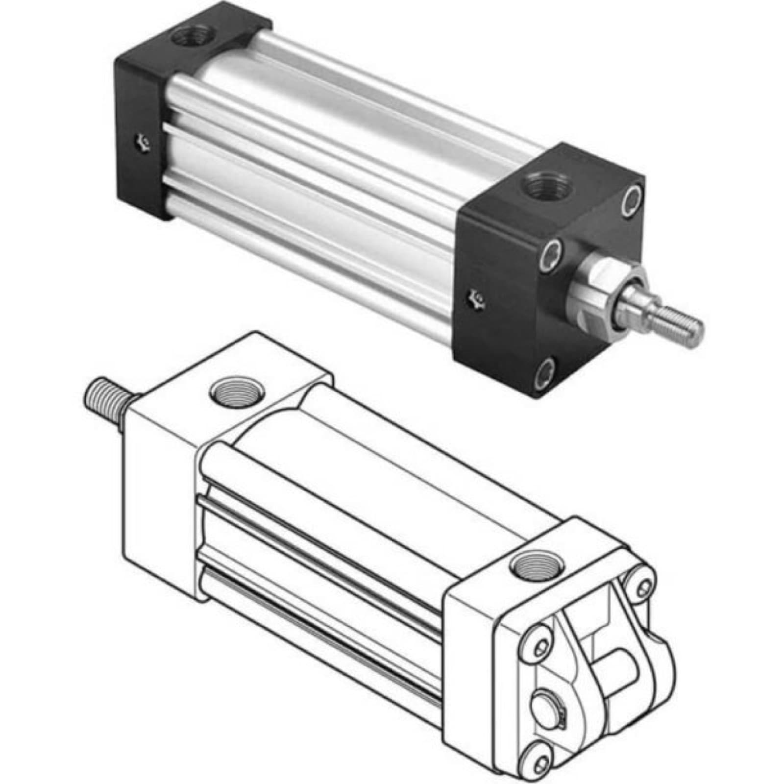 IH-PAR-4MA-SERIES-TIE-ROD-PNEUMATIC-CYLINDERS-2-INCH-4Parker 4MA Series Tie Rod Pneumatic Cylinders, 2 Inch Bore, LipSeals And Magnetic RingParker Hannifin
- IH-PAR-P1F-SERIES-TIE-ROD-PNEUMATIC-CYLINDERS-SMOOTH-4Parker P1F Series Tie Rod Pneumatic Cylinders, Smooth Profile, 40mm BoreParker Hannifin
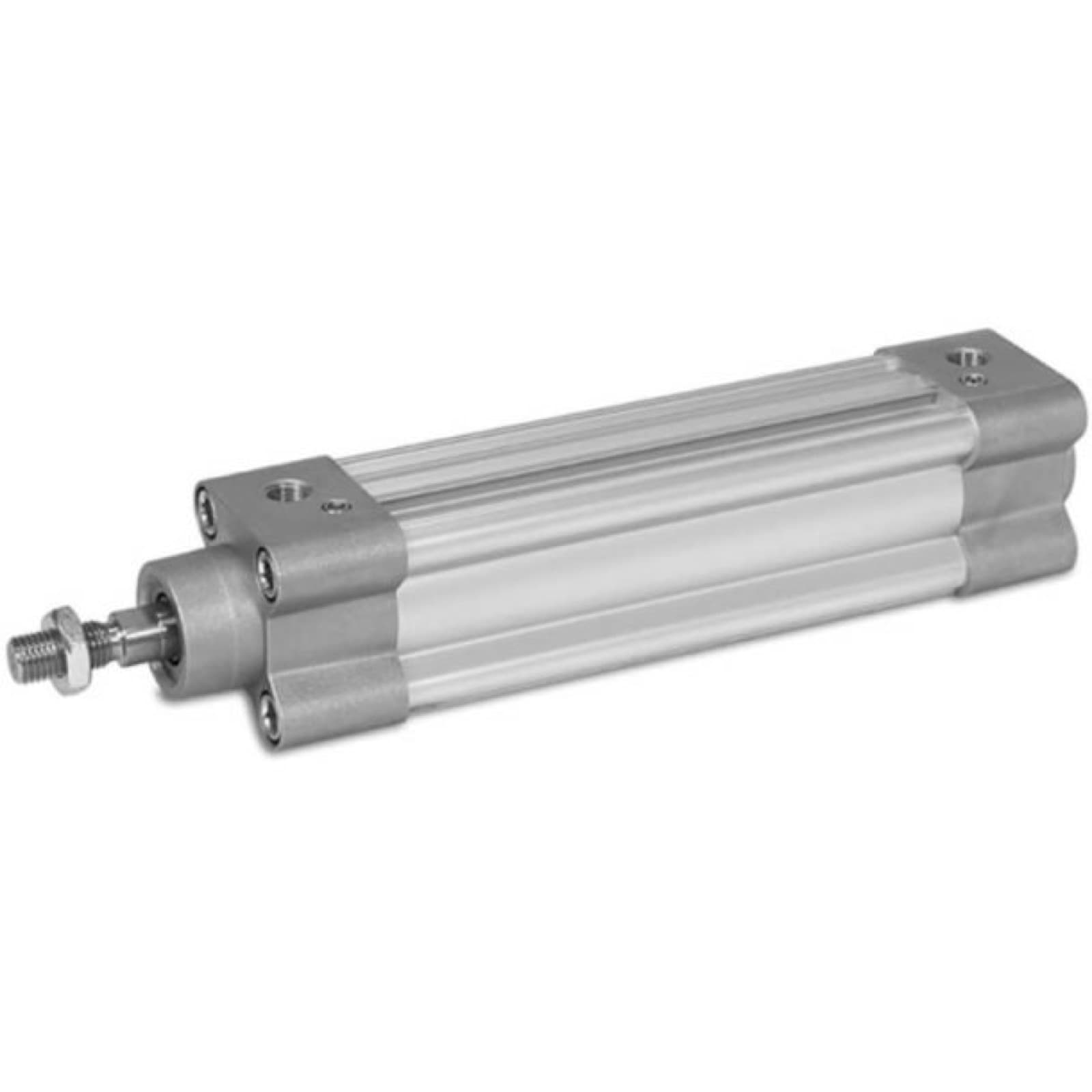 IH-PAR-P1F-SERIES-TIE-ROD-PNEUMATIC-CYLINDERS-SMOOTH-PROParker P1F Series Tie Rod Pneumatic Cylinders, Smooth Profile, 100mm BoreParker Hannifin
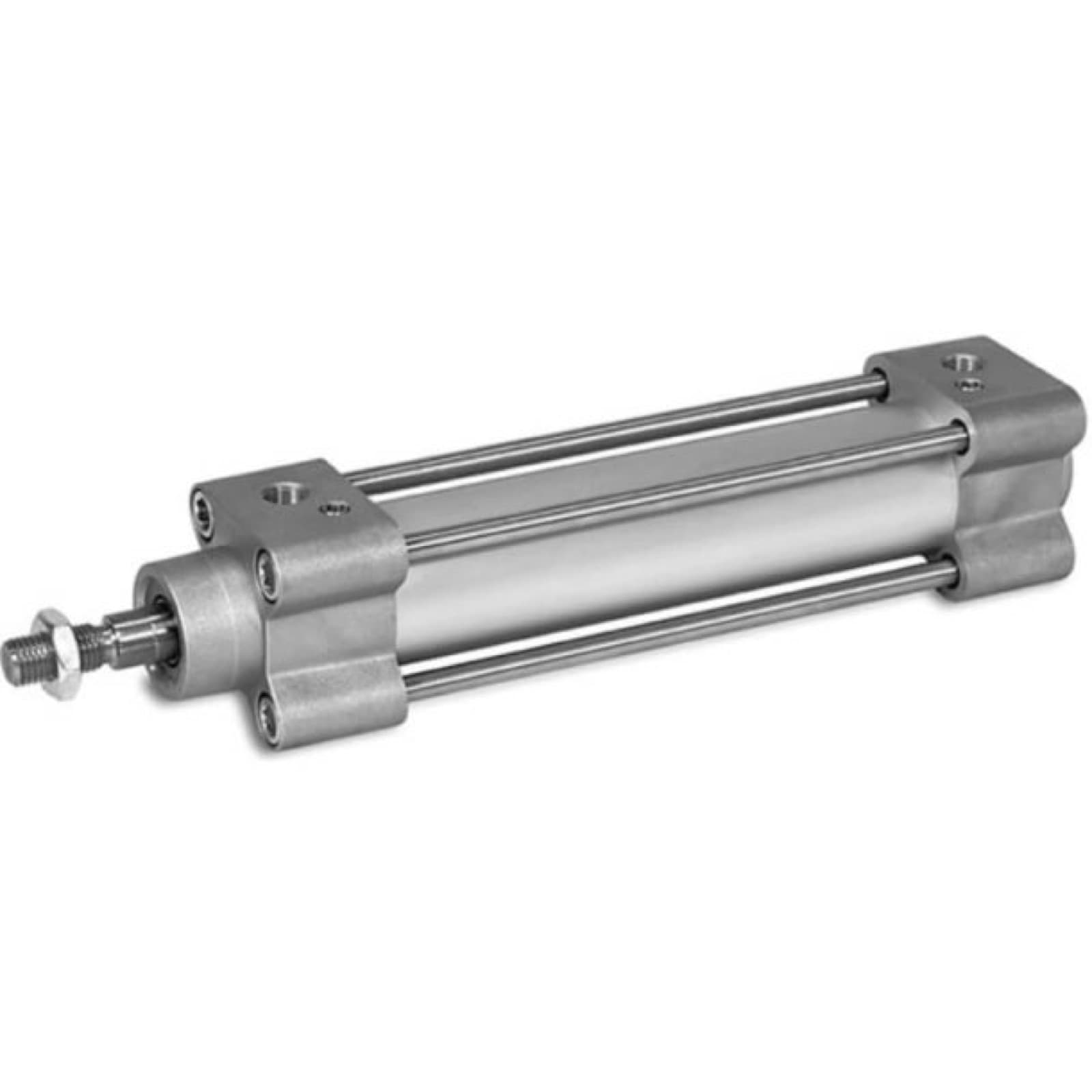 IH-PAR-P1F-SERIES-TIE-ROD-PNEUMATIC-CYLINDERS-TIE-ROD-16Parker P1F Series Tie Rod Pneumatic Cylinders, Tie-Rod, 160mm BoreParker Hannifin
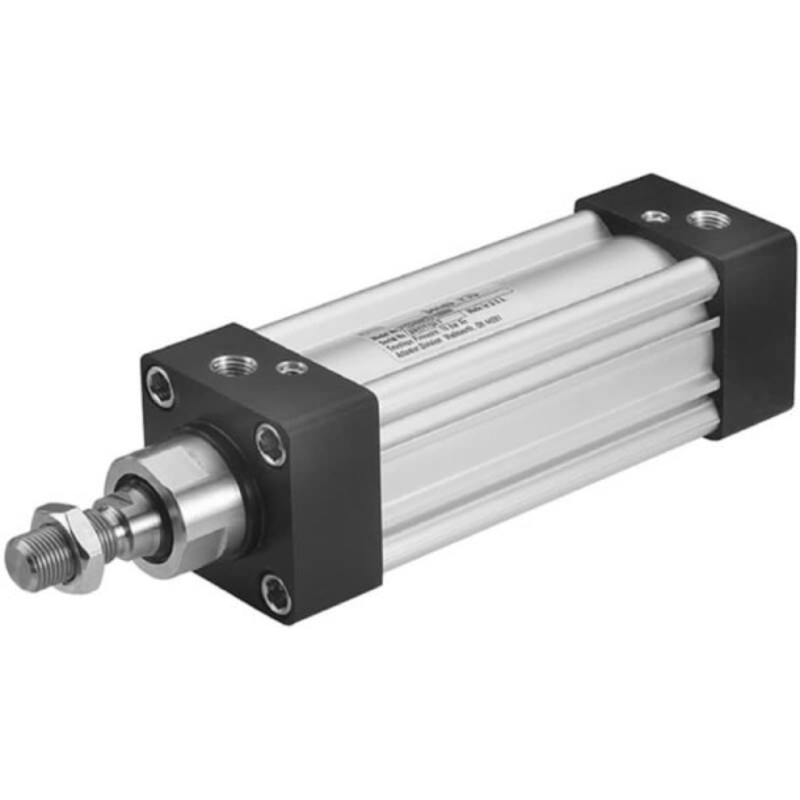 IH-PAR-P1D-SERIES-TIE-ROD-PNEUMATIC-CYLINDERS-COMPOS-4Parker P1D Series Tie Rod Pneumatic Cylinders, Composite Piston, NPTF Ports, Female Rod EndParker Hannifin
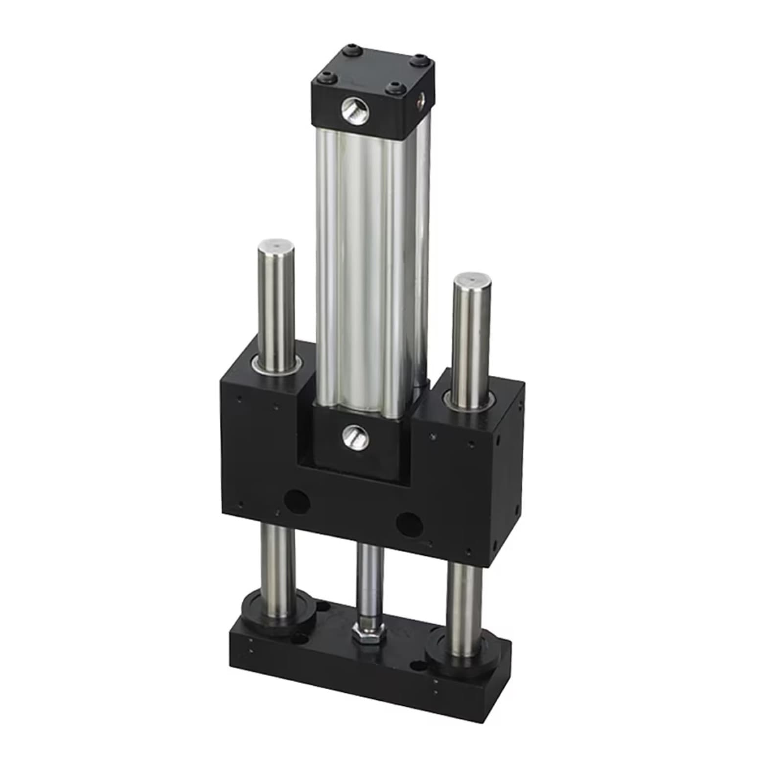 IH-PAR-HB-SERIES-GUIDED-PNEUMATIC-CYLINDERS-COMPACT-SLIDParker HB Series Guided Pneumatic Cylinders, Compact SlideParker Hannifin
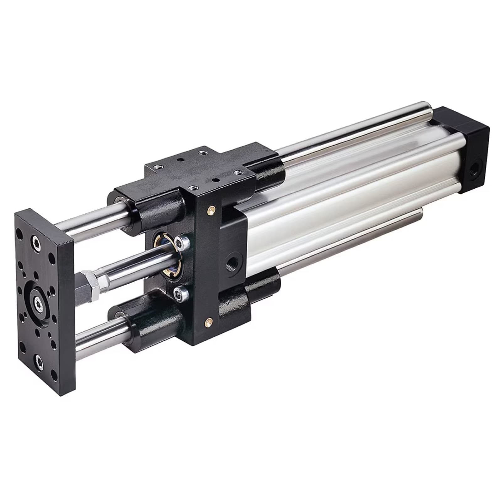 IH-PAR-P5E-SERIES-GUIDED-PNEUMATIC-CYLINDERS-COMPOSITE-BParker P5E Series Guided Pneumatic Cylinders, Composite Bearing, Chrome Plated Oversize ShaftParker Hannifin