An undersized valve is the commonest reason a new pneumatic machine misses its cycle time, and an oversized one wastes money, cabinet space and switching speed. Valve flow is published in at least four different ways — Cv, Kv, effective area S, and the ISO 6358 pair C and b — and they do not convert neatly. This guide explains each rating in plain words, then walks through a maker’s published method for picking a valve to suit a cylinder.
/01Cv and Kv: the water ratings.
Cv (flow coefficient) is the flow of water in US gallons per minute that passes a valve with a 1 psi pressure drop. It came from process-control valves and is the figure most North American pneumatic catalogues still print. Kv is the metric equivalent: cubic metres of water per hour at a 1 bar pressure drop.
Because both are water ratings, the conversion between them is pure unit arithmetic: 1 US gal/min is 0.2271 m³/h and 1 psi is 0.06895 bar, so Kv = Cv × 0.2271 ÷ √0.06895 ≈ 0.865 × Cv, and Cv ≈ 1.156 × Kv.
The problem is that air is compressible. As the pressure drop across a valve grows, the air speeds up until it reaches sonic velocity in the narrowest passage; beyond that point (“choked flow”) lowering the outlet pressure further does not increase the flow. Writing in Machine Design in 2001, N. Oneyama of SMC’s technology research division pointed out that the ANSI Cv for air is measured at a tiny pressure drop — pressure ratios of 0.98 to 0.99, at the extreme end of the subsonic range — so it gives one representative point and says nothing about where the valve chokes. His example: two valves with identical Cv of 0.2 can differ by more than 30% in maximum flow if their critical pressure ratios are 0.1 and 0.5. His conclusion was blunt: Cv alone is not enough to select a valve for a pneumatic actuator.
/02Sonic conductance C and critical pressure ratio b (ISO 6358).
ISO 6358 describes a pneumatic component by its whole flow curve, using two measured numbers:
- Sonic conductance, C — the maximum flow at choked conditions per unit of upstream absolute pressure, usually published in dm³/(s·bar). Think of it as the size of the hole the air sees.
- Critical pressure ratio, b — the ratio of downstream to upstream absolute pressure at which the flow reaches its maximum. A low b means the valve keeps increasing its flow over a wider range of pressure drops; Oneyama notes that b varies from one valve design to another.
With C and b you can calculate the flow at any working pressure and pressure drop, not just at the 1 psi point. SMC has published measured C and b for its valve series since 2000, with Cv and the Japanese effective area S as secondary figures.
Effective area S (mm²) is the older JIS rating, still printed by SMC — its SY5000 page, for example, gives 10.6 mm² (Cv 0.59) body-ported and 12.6 mm² (Cv 0.7) base-mounted for the series. SMC gives two rough conversions: S ≈ 5 × C, and a reference Cv ≈ S ÷ 18, which it says corresponds to valves with b between 0.3 and 0.5. Treat any conversion as approximate: Oneyama notes that the ISO, JIS and ANSI/NFPA standards all allow a 15% variation in the measured figures.
| Rating | Defined as | Units | Who prints it | Limitation |
|---|---|---|---|---|
| Cv | Water flow at 1 psi pressure drop | US gal/min | North American catalogues, Parker’s included | One point at a tiny pressure drop; does not show choking |
| Kv | Water flow at 1 bar pressure drop | m³/h | Metric and process-valve catalogues | Same as Cv; Kv ≈ 0.865 × Cv |
| S (effective area) | Equivalent orifice area at choked flow (JIS) | mm² | SMC | Maximum flow only; S ≈ 5 × C |
| C and b (ISO 6358)Highlighted | Sonic conductance and critical pressure ratio | dm³/(s·bar), dimensionless | SMC and other makers testing to ISO 6358 | Needs both numbers; the most complete description |
/03Matching a valve to a cylinder: Parker’s method.
The question a valve size answers is: how much air must pass, in what time, with how much pressure lost on the way? Chris Landis, valve and vacuum product manager at Parker Hannifin, set out Parker’s method in Machine Design (2007). In outline:
- Cylinder volume. V = (π/4) × d² × l, where d is the bore and l the stroke. Use the annulus area (bore minus rod) for the retract stroke.
- Compression ratio. Cr = P1 ÷ Pa, the absolute supply pressure divided by atmospheric pressure (14.7 psi). Each cubic inch of cylinder at working pressure takes Cr cubic inches of free air.
- Free-air flow. Q = V × Cr ÷ (28.8 × t), with V in cubic inches and t the stroke time in seconds, gives scfm. (The 28.8 converts cubic inches per second to cubic feet per minute: 1,728 ÷ 60.)
- Required Cv. Cv = Q × A, where A is a constant Parker tabulates for the inlet pressure and the pressure drop you allow across the valve. It comes from the standard gas-flow equation, with air’s specific gravity and absolute temperature built in.
On the pressure drop, Parker’s guidance is: assume 5 psi for most work; use 2 psi for time- or process-critical applications; a 10 psi drop is often acceptable and permits smaller, cheaper valves. Its worked charts assume 80 psig at the valve, based on a typical plant running at 100 psig with line losses. Note that l ÷ t is only the average rod speed — the cylinder accelerates from rest — so build in margin.
A worked example from Festo
Michael Foy, a design engineer at Festo, worked the same calculation in metric for Machine Design (2003): a 25 mm bore, 100 mm stroke cylinder with a 10 mm rod, at 6 bar with a 0.25 bar pressure drop, extending in 0.25 s and retracting in 0.2 s. With a compression factor of 7 ((6 + 1) ÷ 1), he arrived at a required Cv of 0.158 to extend and 0.166 to retract, and selected a valve of Cv 0.200. Note that the faster retract stroke, not the larger extend volume, set the size.
Three practical checks once you have a target Cv:
- Compare like with like. If one maker prints C and b and another prints Cv, convert carefully or ask for the same rating. A valve that looks larger on Cv may choke earlier.
- Look at the whole path. The tubing bore and the fittings often restrict more than the valve. Our guides to pneumatic tubing and push-to-connect fittings and silencers cover those parts of the circuit.
- Remember the exhaust. The air leaving the cylinder must pass back through the valve and out through the silencer. A restrictive silencer or a meter-out flow control slows the stroke as surely as a small valve; see cylinder speed control and quick exhaust valves.
We do not publish flow figures on our listings: we sell by maker part number, and flow varies within a series by body type, port and function. Ask us for the maker’s data sheet for the exact part number.
/04ISO 5599-1 plug-in valves vs maker manifolds.
Most machines with more than a handful of valves mount them on a manifold, which shares a common supply and common exhaust galleries and cuts the tubing and fittings needed. There are two families:
ISO interchangeable
ISO 5599-1 fixes the sub-base mounting interface for five-port valves — Parker’s range covers sizes 1, 2 and 3 — and ISO 5599-2 covers the version with an integrated electrical connector. ISO 15407 does the same for the smaller 18 mm and 26 mm widths. Parker notes that its plug-in valves meet ISO 15407 and 5599 dimensional and electrical standards. The point of the standard is interchangeability: a size-1 ISO valve from one maker should fit a size-1 ISO sub-base from another. Our Parker H-ISO H1, HA and HB listings are valves of this kind.
Maker-proprietary manifolds
SMC’s SY, VQZ, VQ, VF and VFS valves, ARO’s Alpha, MaxAir and Sierra lines and Numatics’ manifold blocks are designed around their own manifold bases. They are generally more compact for a given flow and offer more electrical options — multi-pin, fieldbus, plug-in wiring — but a valve from one maker will not fit another maker’s base, and often not a different series from the same maker. When replacing a single valve on such a manifold, quote the manifold part number as well as the valve.
Common vs individual exhaust
On a common-exhaust manifold, all valves exhaust into one shared gallery. When several valves exhaust at once — or the shared silencer is restrictive or clogged — the gallery pressure rises, and that back-pressure can push into the outlets of other valves and nudge a cylinder or single-acting actuator that should be at rest. SMC offers back-pressure check valves and individual-exhaust options on its manifold series for this reason. Specify individual exhaust (or back-pressure checks) when a manifold drives single-acting cylinders, vacuum ejectors or sensitive actuators, or when exhaust air must be piped away from the machine.
| Option | Interchangeable between makers? | Strengths | Best for |
|---|---|---|---|
| Body-ported single valve | No (port threads only) | Simple; valve can sit close to the cylinder | One-off valves, long distances between actuators |
| ISO 5599-1 sub-base (sizes 1, 2, 3) | Yes, at the interface | Second-source replacement; larger flows | Heavy-duty and large-bore cylinders, long-life plant |
| ISO 15407 (18 mm, 26 mm) | Yes, at the interface | Compact ISO option | Smaller cylinders with an interchangeability requirement |
| Maker manifold (SMC, ARO, Numatics, Parker) | No | Compact, high flow per width, fieldbus and multi-pin wiring | Automation machines with many valves |
Choosing a valve size
IfDo you know bore, stroke, pressure and stroke time?
Work out Q and the required Cv by Parker’s method, at a 5 psi drop (2 psi if timing is critical).
IfMaker publishes C and b?
Use them — they describe the whole flow curve; Cv is a single point.
IfLong tube runs or many fittings?
Add margin or size up the tube; the valve is not the only restriction.
IfMust second-source replacements fit the same base?
ISO 5599-1 or ISO 15407 valves.
IfManifold drives single-acting cylinders or vacuum?
Individual exhaust or back-pressure check valves on those stations.
Common questions
- What is Cv on a pneumatic valve?
- The flow of water in US gallons per minute that passes the valve at a 1 psi pressure drop. It is a convenient comparison figure, but on compressed air it describes only one point of the flow curve.
- How do I convert Cv to Kv?
- Kv ≈ 0.865 × Cv, and Cv ≈ 1.156 × Kv. Both are water ratings, so the conversion is exact unit arithmetic.
- What is sonic conductance in a pneumatic valve?
- The ISO 6358 measure of a valve’s maximum (choked) air flow per unit of upstream absolute pressure, usually in dm³/(s·bar). It is published with the critical pressure ratio b, which says where the flow chokes.
- How do I size a solenoid valve for a pneumatic cylinder?
- Calculate the cylinder volume, multiply by the compression ratio to get free air, divide by the stroke time to get flow, then find the Cv that passes that flow at an allowed pressure drop — Parker suggests 5 psi. Add margin for fittings and tubing.
- Should the valve port size match the cylinder port size?
- Not necessarily. Festo notes that smaller valves switch faster, cost less and use less power. Size on the flow the cylinder needs, then use a flow control if it runs too fast.
- What is an ISO 5599 valve?
- A five-port valve built to the ISO 5599-1 sub-base interface (sizes 1, 2 and 3 and up), so valves of the same size from different makers fit the same base. ISO 5599-2 adds an integrated electrical connector.
- What is the difference between common and individual exhaust on a valve manifold?
- With common exhaust, all valves vent into one gallery and back-pressure can affect idle actuators. Individual exhaust gives each station its own exhaust path; SMC also offers back-pressure check valves for the same problem.
/05What we list.
Every listing on our solenoid valves shelf — single valves, ISO valves and maker manifolds from SMC, Parker, ARO and Numatics — sold by maker part number; ask for the maker’s flow data for any part.
- ARO 200 Series Circuitry Valves
- ARO 50 Series Pneumatic Valves
- ARO Air Control Valves
- ARO Alpha Series Pneumatic Valves
- ARO Alpha Series Thin Manifolds
- ARO CAT Series High Flow Valves
- ARO CAT Series Miniature 3 & 4-Way Valves
- ARO CAT Series Valves, 1/8" Port Size
- ARO E Series Pneumatic Valves
- ARO H Series Pneumatic Valves
- ARO K Series Pneumatic Valves
- ARO MaxAir Series Manifolds
- ARO MaxAir Series Pneumatic Valves
- ARO Sierra 15 Base-Mounted Valves
- ARO Sierra 15 Body-Ported Valves
- ARO Sierra 18 Pneumatic Valves
- ARO Sierra Series Manifolds, High Profile
- ARO Sierra Series Manifolds, Low Profile
- ARO Solenoid Air Control Valves
- Numatics Manifold Block
- Numatics Manifold Block 3 Stations
- Numatics Manifold Block 4 Stations, Npt
- Numatics Manifold Block 6 Stations, Npt
- Numatics Solenoid Air Control Valve 4-Way, 2-Position
- Numatics Solenoid Air Control Valve 4-Way, 2-Position, 5-Port
- Numatics Solenoid Air Control Valve 4-Way, 2-Position, 5-Port, Detented
- Numatics Solenoid Air Control Valve 4-Way, 3-Position, 5-Port
- Parker B Series Double Solenoid Valves, 4-Way 2-Position
- Parker B Series Single Solenoid Valves, 4-Way 2-Position
- Parker B series, Solenoid Air Control Valve 4-Way, 3-Position
- Parker H-ISO H1 Series Double Solenoid Valves, 4-Way 2-Position
- Parker H-ISO H1 Series Single Solenoid Valves, 4-Way 2-Position
- Parker H-ISO HA Series Double Solenoid Valves, 4-Way 2-Position
- Parker H-ISO HA Series Double Solenoid Valves, 4-Way 3-Position
- Parker H-ISO HA Series Single Solenoid Valves, 4-Way 2-Position
- Parker H-ISO HB Series Double Solenoid Valves, 3-Way 2-Position
- Parker H-ISO HB Series Double Solenoid Valves, 4-Way 3-Position
- Parker H-ISO HB Series Single Solenoid Valves, 4-Way 2-Position
- Parker Solenoid Air Control Valve 2 Way, Normally Closed
- Parker Solenoid Air Control Valve 3 Position, All Ports Blocked
- Parker Solenoid Air Control Valve 3-Position
- Parker Solenoid Air Control Valve 3-Way, 2-Position
- Parker Solenoid Air Control Valve 4-Way, 2-Position
- Parker Solenoid Air Control Valve 4-Way, 2-Position, 5-Port
- Parker Valvair II Series Manifold
- SMC LVM Series Chemical Valve
- SMC PVQ Series Proportional Valve
- SMC Solenoid Air Control Valve 4-Way, 3-Position
- SMC Solenoid Air Control Valve 5-Way, 2-Position
- SMC Solenoid Air Control Valve 5-Way, 2-Position, 5-Port
- SMC Solenoid Air Control Valve 5-Way, 3-Position
- SMC Solenoid Air Control Valve 5-Way, 3-Position, 5-Port
- SMC SS3Y1 Series Manifold
- SMC SS3YJ5 Series Manifold
- SMC SS3YJ7 Series Manifold
- SMC SS5V1 Series Manifold
- SMC SS5Y3 Series Manifold
- SMC SS5Y5 Series Manifold
- SMC SS5YJ7 Series Manifold
- SMC SY3000 Series Valve
- SMC SY5000 Series Valve
- SMC SY7000 Series Manifold
- SMC Two Port Process Valve
- SMC Valve
- SMC Valve Manifold
- SMC Valve Manifold 4 Station
- SMC Valve Manifold 6 Station
- SMC Valve Manifold 8 Station
- SMC VDW Series Valve
- SMC VEP Series Proportional Valve
- SMC VEX Series Proportional Valve
- SMC VF Series Manifold
- SMC VFR Series Manifold
- SMC VFS Series Manifold
- SMC VFS Series Manifold, VV5FS2 1/4 Base Mount
- SMC VG Series Valve
- SMC VJ3000 Series Solenoid Valve
- SMC VQ Series Manifold
- SMC VQ4000 Series Valve
- SMC VQ5000 Series Valve
- SMC VQZ1000 Series Valve
- SMC VQZ200 Series Valve
- SMC VQZ2000 Series Valve
- SMC VQZ300 Series Valve
- SMC VQZ3000 Series Valve
- SMC VT4 Series Solenoid Valve
- SMC VV3Q Series Manifold
- SMC VV5Q Series Manifold
- SMC VV5Q41 Series Manifold
- SMC VV5QC21 Series Manifold
- SMC VV5QC41 Series Manifold
- SMC VV5Z Series Manifold
- SMC VV7 Series Manifold
- SMC VV81 Series Manifold
- SMC VX Series Manifold
- SMC VX2 Series 2-Way Media Valve
- SMC VZS Series Manifold
ISO valves and valve manifolds
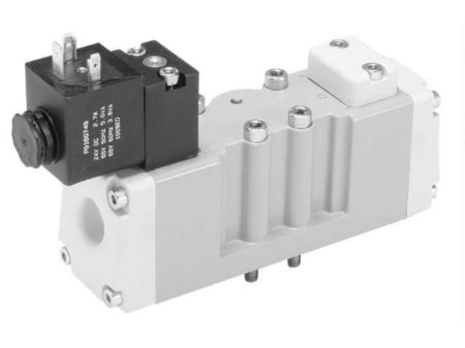 IH-PAR-H-ISO-H1-SERIES-SINGLE-SOLENOID-VALVES-4-WAY-2-POParker H-ISO H1 Series Single Solenoid Valves, 4-Way 2-PositionParker Hannifin
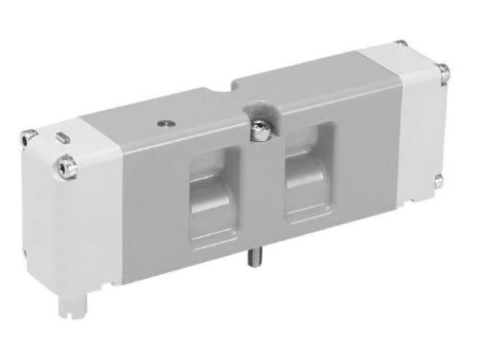 IH-PAR-H-ISO-HA-SERIES-SINGLE-SOLENOID-VALVES-4-WAY-2-POParker H-ISO HA Series Single Solenoid Valves, 4-Way 2-PositionParker Hannifin
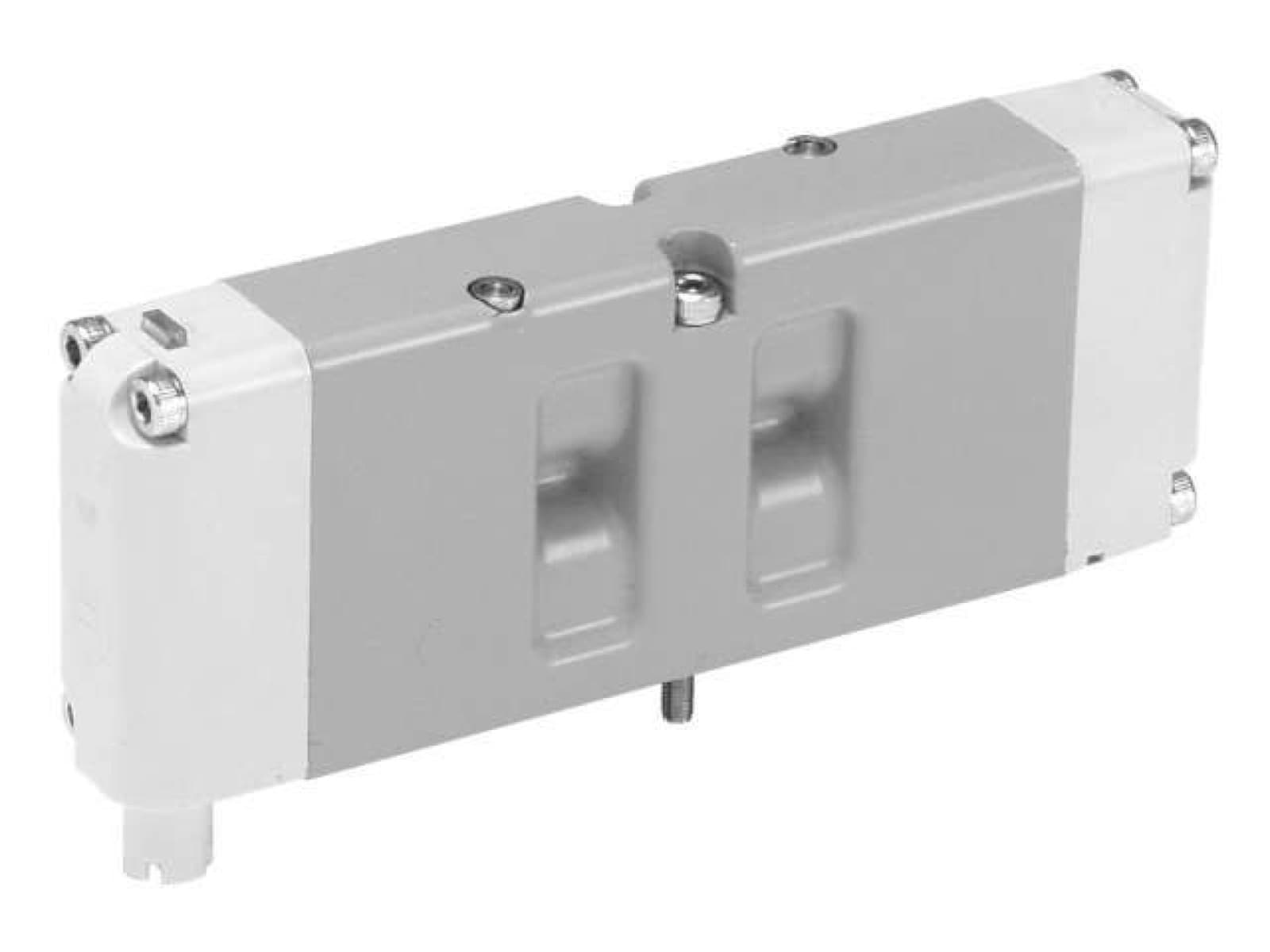 IH-PAR-H-ISO-HB-SERIES-SINGLE-SOLENOID-VALVES-4-WAY-2-POParker H-ISO HB Series Single Solenoid Valves, 4-Way 2-PositionParker Hannifin
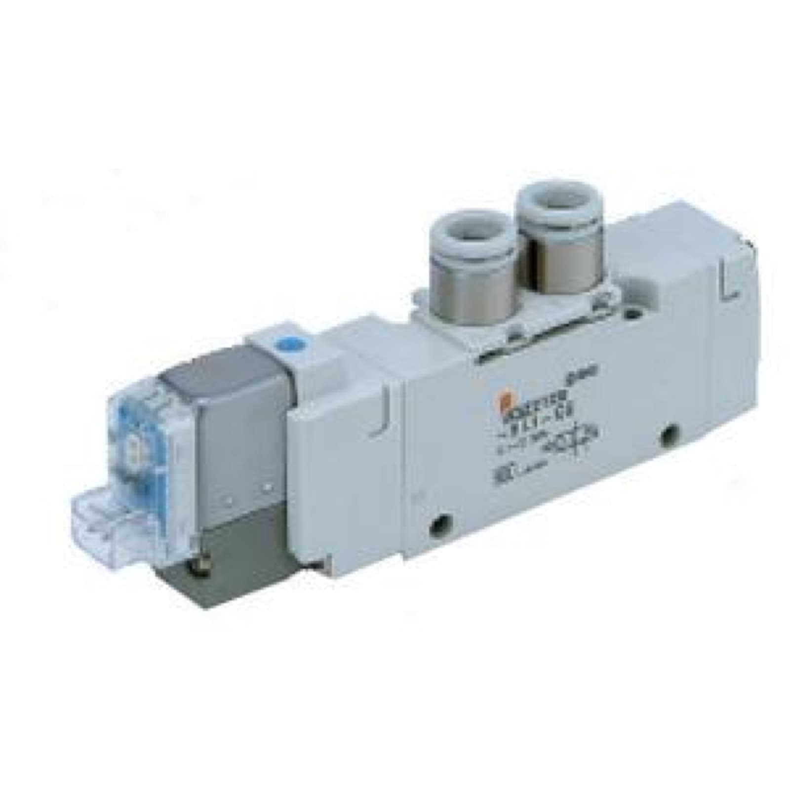 IH-SMC-VQZ2000-SERIES-VALVESMC VQZ2000 Series ValveSMC
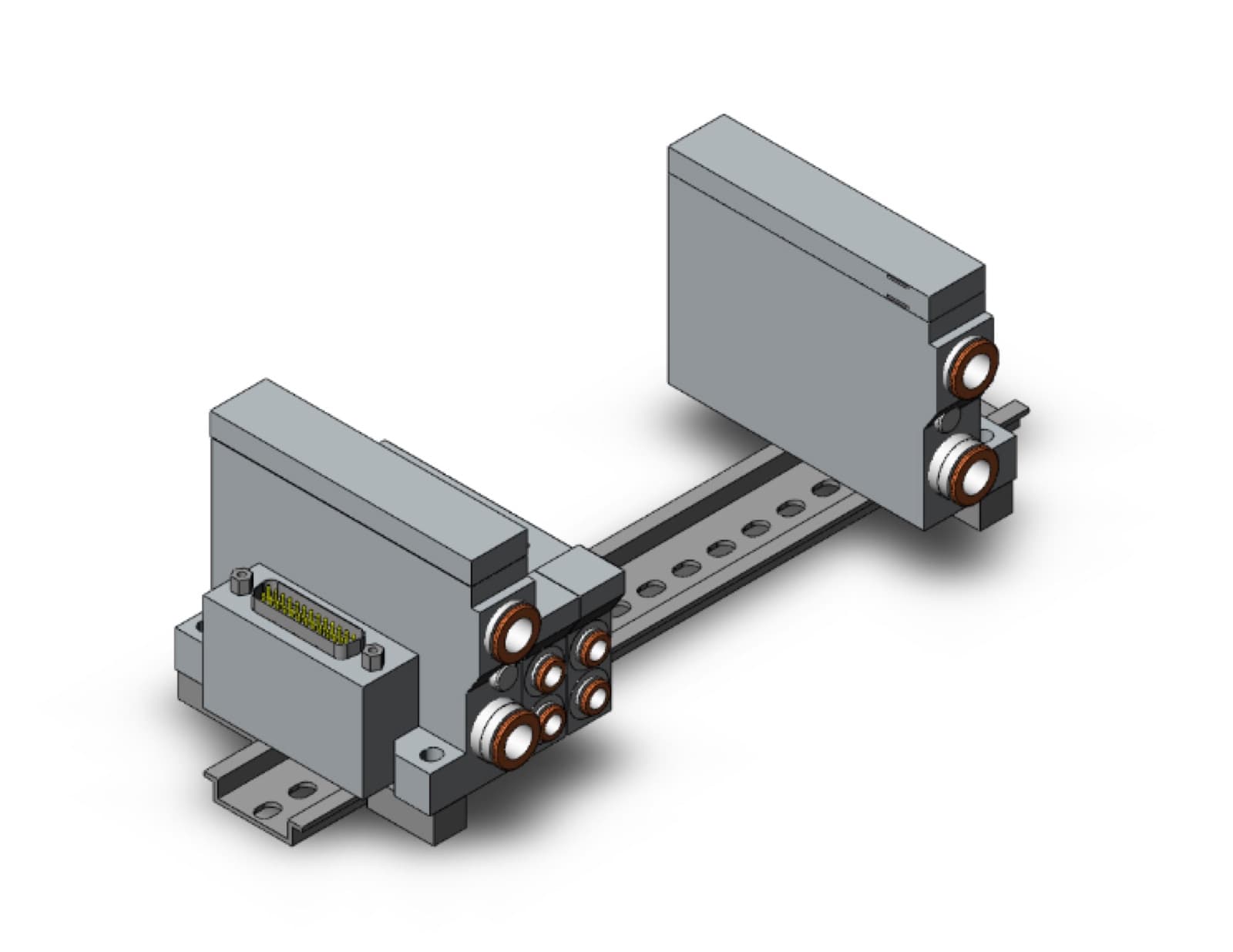 IH-SMC-VV5Q-SERIES-MANIFOLDSMC VV5Q Series ManifoldSMC
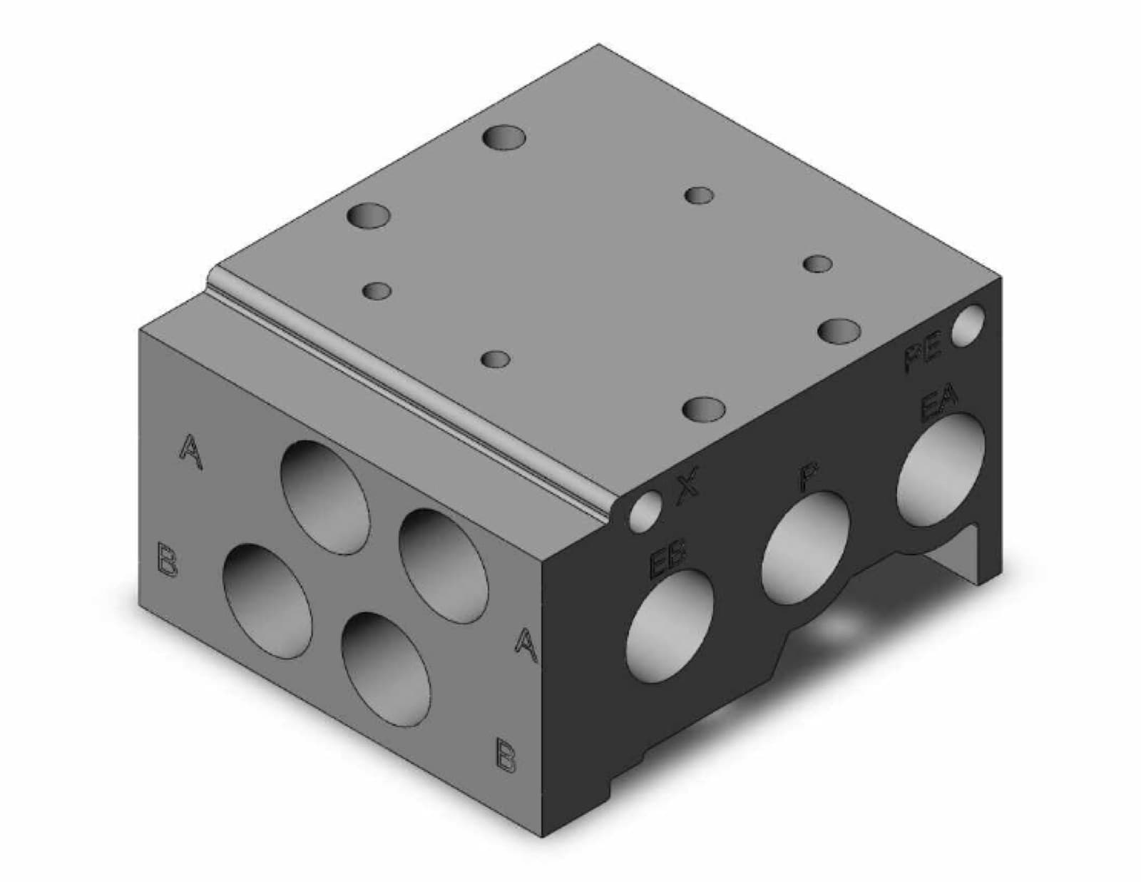 IH-SMC-SS5Y5-SERIES-MANIFOLDSMC SS5Y5 Series ManifoldSMC
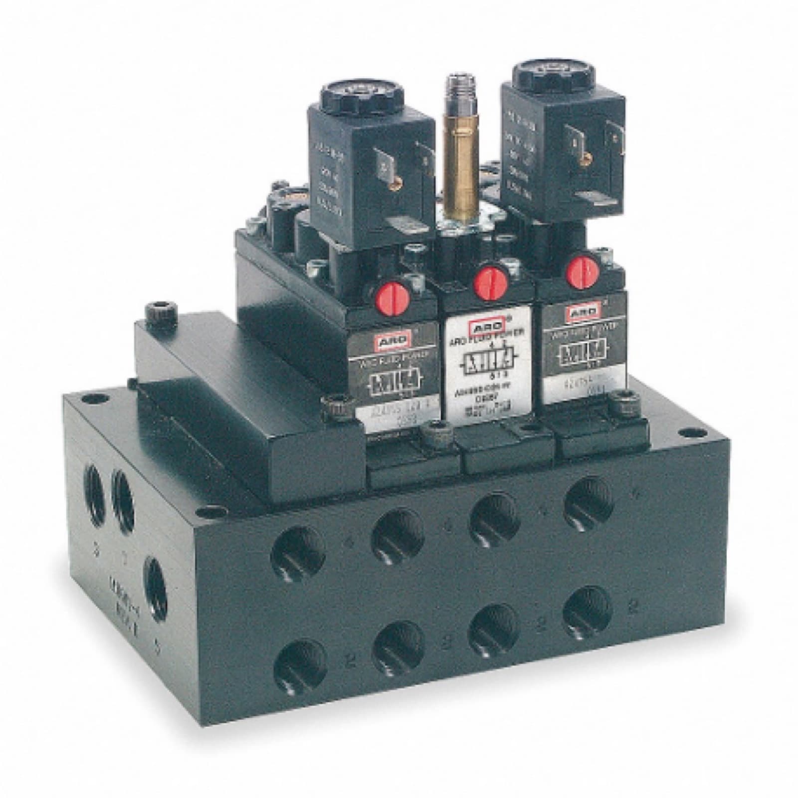 IH-ARO-ALPHA-SERIES-THIN-MANIFOLDSARO Alpha Series Thin ManifoldsARO
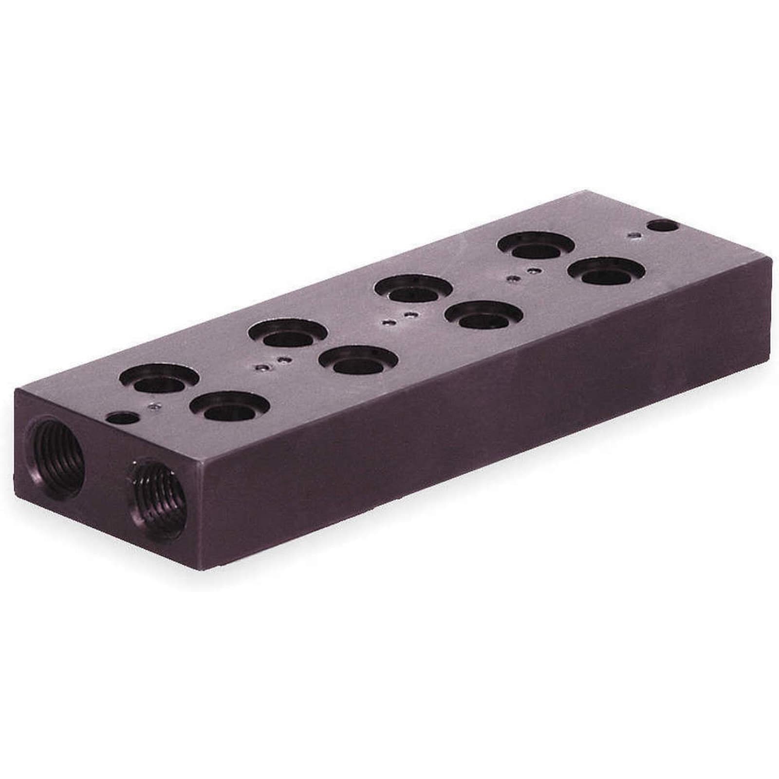 IH-NUM-MANIFOLD-BLOCK-4-STATIONS-NPTNumatics Manifold Block 4 Stations, NptNumatics