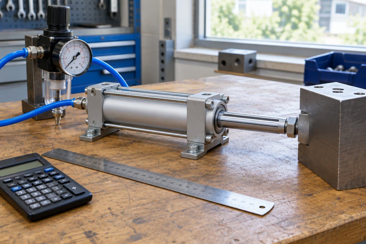
An air cylinder sized at the compressor’s pressure, with no margin for friction or acceleration and only for the extend stroke, looks right on paper and stalls or crawls on the machine. This guide works through the sizing the way the makers’ catalogues do: force from pressure and area, the margin Parker recommends, the pressure the cylinder actually sees, and the air it will use.
/01Force is pressure times area.
A cylinder’s theoretical force is the air pressure multiplied by the area it acts on:
- Extend (push): F = p × A, where A = π/4 × D² for bore D.
- Retract (pull): F = p × (A − a), where a = π/4 × d² for rod diameter d. The rod covers part of the piston on that side, leaving the annulus.
Keep the units consistent. In metric, 1 bar = 0.1 N/mm², so force in newtons = pressure in bar × 0.1 × area in mm². In inch units, pressure in psi × area in in² gives force in lbf directly.
Check: a 50 mm bore has an area of π/4 × 50² = 1,963 mm². At 6 bar (0.6 N/mm²) that is 1,178 N. With the 20 mm rod Parker fits to its 50 mm P1D and P1F, the annulus is 1,963 − 314 = 1,649 mm², so the retract force is 990 N — 16% less. Parker’s published force tables for P1D and P1F give the same 1,178 N and 990 N.
This is theoretical force. It ignores seal friction, the force needed to accelerate the load, and back-pressure from the exhausting side — which is why the makers tell you to leave margin.
| Bore / rod (mm) | Piston area (mm²) | Extend at 6 bar (N) | Annulus (mm²) | Retract at 6 bar (N) |
|---|---|---|---|---|
| 32 / 12 | 804 | 483 | 691 | 415 |
| 40 / 16 | 1,257 | 754 | 1,056 | 633 |
| 50 / 20Highlighted | 1,963 | 1,178 | 1,649 | 990 |
| 63 / 20 | 3,117 | 1,870 | 2,803 | 1,682 |
| 80 / 25 | 5,027 | 3,016 | 4,536 | 2,721 |
| 100 / 25 | 7,854 | 4,712 | 7,363 | 4,418 |
| 125 / 32 | 12,272 | 7,363 | 11,468 | 6,881 |
| Bore (in) | Piston area (in²) | Extend at 80 psi (lbf) | Extend at 80 psi (N) |
|---|---|---|---|
| 3/4 | 0.442 | 35 | 157 |
| 1 | 0.785 | 63 | 279 |
| 1-1/2 | 1.767 | 141 | 629 |
| 2Highlighted | 3.142 | 251 | 1,118 |
| 2-1/2 | 4.909 | 393 | 1,747 |
| 3-1/4 | 8.296 | 664 | 2,952 |
| 4 | 12.566 | 1,005 | 4,472 |
| 5 | 19.635 | 1,571 | 6,987 |
| 6 | 28.274 | 2,262 | 10,062 |
| 8 | 50.265 | 4,021 | 17,887 |
/02How much margin: the load ratio.
The load ratio is the force the job needs divided by the cylinder’s theoretical force. The makers publish guidance, and it is worth quoting them exactly because they frame it differently:
- Parker, P1F catalogue: the cylinder load should be about 50% of the theoretical force, which Parker calls the normal load. A lower load gives a higher velocity, and vice versa.
- Parker, P1D catalogue: select a theoretical force 50–100% larger than the force required — that is, a load ratio between about 67% and 50%.
Read together: 50% is the comfortable figure for a cylinder that has to move briskly; up to about two-thirds is acceptable where speed matters less. Above that, the cylinder will move, but slowly and unevenly, and Parker’s cushioning data shows a second penalty — when the pressure drop across the piston exceeds 1 bar, Parker says to cut the moving mass by a factor of 2.5, or the speed by 1.5, against its cushioning diagram.
What counts as “load”
Parker defines it as the sum of internal and external friction plus any gravitational forces. So for a cylinder lifting vertically, the weight is load; for a cylinder pushing a carriage on guides, the guide friction is load; for a cylinder pulling, size on the annulus, not the bore.
Clamping and pressing are different
A clamp or press cylinder does its work stationary at the end of its travel, so it delivers its full theoretical force there. SMC makes the related point about buckling: once the rod is stopped by an external stopper, the full force the cylinder generates acts on the cylinder itself, however light the load was. Size a clamp on the force needed at the pressure you can guarantee — and check rod buckling, covered in our cushioning and mounting guide.
/03Use the pressure at the cylinder, not at the compressor.
A compressor may be set to 8 bar while the cylinder works at 5.5. Between them sit a dryer, the distribution main, an FRL whose regulator is set below line pressure, a valve and the tubing to the port. Parker’s force tables are given against the pressure applied to the cylinder, and its P1D cushioning diagram explicitly assumes 6 bar at the cylinder port.
- Size on the regulated pressure, at the lowest setting the machine will run, not the compressor cut-in or cut-out.
- Expect less while the cylinder moves. Parker’s tubing guidance is that an undersized tube between valve and cylinder throttles the flow and limits speed. The faster the stroke, the more the port pressure falls below the regulator setting during motion.
- Stay inside the rating. Parker’s P1D and P1F are rated to 10 bar; SMC’s C96 to 1.0 MPa; Parker’s 4MA to 250 psig for air service.
Wet, hot air
Parker specifies air to ISO 8573-1 class 3.4.3 for P1D and P1F — a 5 µm filter and a +3 °C pressure dew point for indoor use, with a lower dew point outdoors. SMC asks for a filter of 5 µm or finer upstream of the valve and an aftercooler, dryer or water separator where there is a lot of condensate. In a Gulf summer the air entering the compressor is hot and humid, and the water it carries condenses downstream as the air cools; treat the dryer and drains as part of the cylinder’s specification, not an extra. Our ISO 8573-1 guide explains the classes.
/04Air consumption, per cycle and in free air.
A double-acting cylinder fills the bore side to extend and the annulus side to retract. The compressed volume per cycle is:
V = (A + (A − a)) × stroke
Compressors are rated in free air — air at atmospheric pressure — so convert by the absolute pressure ratio:
Free air per cycle = V × (p + 1.013) ÷ 1.013 (p in bar gauge), or V × (p + 14.7) ÷ 14.7 (p in psig).
Multiply by cycles per minute for l/min (or ft³/min, scfm, in inch units: 1 ft³ = 1,728 in³ = 28.3 l).
This is the basis of Parker’s own table. For a 63 mm P1F at 6 bar: bore area 31.2 cm² × 1 cm × (6 + 1.013) ÷ 1.013 = 216 cm³ per 10 mm of extend stroke — Parker’s table gives 0.216 l. Parker’s P1D table states the same thing as free air per 10 mm of stroke for a double stroke at 6 bar.
Two things push the real figure up. The tube between valve and cylinder fills and exhausts every cycle too — Parker warns that an oversized tube creates dead volume that increases air consumption and filling time. And leaks anywhere in the circuit add to the compressor’s load whether the cylinder moves or not.
/05Worked example, metric and inch.
Metric: 1,000 N at 5.5 bar
A horizontal cylinder must push a carriage needing 1,000 N including guide friction. The regulator is set to 5.5 bar (0.55 N/mm²). Stroke 300 mm, 12 cycles a minute.
- Parker P1F guidance (load ≈ 50%): theoretical force needed = 2 × 1,000 = 2,000 N. Area = 2,000 ÷ 0.55 = 3,636 mm², so D = √(4 × 3,636 ÷ π) = 68 mm. Next ISO bore: 80 mm, giving 5,027 × 0.55 = 2,765 N — a load ratio of 36%.
- Parker P1D guidance (at least 50% larger): 1.5 × 1,000 = 1,500 N, area 2,727 mm², D = 59 mm. Next bore: 63 mm, giving 3,117 × 0.55 = 1,714 N — a load ratio of 58%.
- Retract check (63/20): annulus 2,803 mm² × 0.55 = 1,542 N, enough if the return needs 1,000 N.
- Choose: 63 mm if speed is not critical; 80 mm if the carriage must move quickly, since Parker notes a lower load ratio gives a higher velocity.
- Air, 63/20: V = (3,117 + 2,803) mm² × 300 mm = 1.776 l. Free air = 1.776 × (5.5 + 1.013) ÷ 1.013 = 1.776 × 6.43 = 11.4 l per cycle; × 12 = 137 l/min (about 4.8 scfm), before tubing dead volume and leaks.
Inch: 225 lbf at 80 psi
Same job in inch units: 225 lbf of load, 80 psi at the cylinder, 8 in stroke, 15 cycles a minute.
- Load ≈ 50%: 450 lbf ÷ 80 psi = 5.63 in², D = 2.68 in. Next bore in Parker’s 4MA range: 3-1/4 in, 8.296 in² × 80 = 664 lbf, load ratio 34%.
- At least 50% larger: 337.5 lbf ÷ 80 = 4.22 in², D = 2.32 in. Next bore: 2-1/2 in, 4.909 in² × 80 = 393 lbf, load ratio 57%.
- Retract: assuming a 5/8 in rod (check the actual rod on the data sheet), rod area = 0.307 in², annulus = 4.602 in², retract force = 368 lbf.
- Air, 2-1/2 in with 5/8 in rod: V = (4.909 + 4.602) × 8 = 76.1 in³. Free air = 76.1 × (80 + 14.7) ÷ 14.7 = 76.1 × 6.44 = 490 in³ = 0.284 ft³ per cycle; × 15 = 4.3 scfm (about 120 l/min).
Sizing checklist
IfDo you know the force at the slowest point, including friction and weight?
If not, measure or estimate it first — that is the load.
IfMoving load that must be quick?
Aim for a load ratio near 50% (Parker P1F guidance).
IfMoving load where speed matters less?
Up to about two-thirds — a theoretical force at least 50% above the load (Parker P1D guidance).
IfPulling, not pushing?
Size on the annulus area, not the bore.
IfClamping or pressing?
Size on the force needed at the guaranteed minimum pressure, then check buckling.
IfIs the pressure you used the regulated pressure at the cylinder?
If it was the compressor setting, resize at the regulator setting.
IfDoes the compressor have spare free-air capacity?
Add up free air per cycle × cycles per minute for every cylinder, plus tubing and leaks.
Common questions
- How do you calculate pneumatic cylinder force?
- Multiply the pressure by the piston area. In metric, force (N) = pressure (bar) × 0.1 × area (mm²); in inch units, force (lbf) = pressure (psi) × area (in²). For the retract stroke, subtract the rod area first.
- Why is the retract force lower than the extend force?
- On the retract stroke the air acts on the annulus — the piston area minus the area covered by the rod — so the same pressure produces less force. With a 50 mm bore and 20 mm rod it is 16% less.
- What load ratio should a pneumatic cylinder run at?
- Parker’s P1F catalogue says the load should be about 50% of theoretical force; its P1D catalogue says select a theoretical force 50–100% larger than required. Use the lower ratio where speed matters.
- What force does a 50 mm cylinder give at 6 bar?
- 1,178 N extending and, with a 20 mm rod, 990 N retracting — theoretical figures before friction and margin.
- How much air does a pneumatic cylinder use?
- Per cycle, (bore area + annulus) × stroke, converted to free air by multiplying by (gauge pressure + 1.013) ÷ 1.013 in bar. A 63 mm cylinder with 300 mm stroke at 5.5 bar uses about 11.4 litres of free air per cycle.
- Should I size a cylinder on compressor pressure?
- No. Use the regulated pressure at the cylinder, at the lowest setting the machine will run. Parker’s force tables and cushioning data are stated at the pressure applied to the cylinder.
/06What we list.
Once you have a bore, stroke and mounting, the listings below cover every cylinder on our shelf — Parker NFPA (4MA, 2MNR) and ISO 15552 (P1D, P1F) tie-rod, SR-family round body, LP compact and HB/P5E guided cylinders, plus Destaco. Each carries the maker’s part numbers.
Parker 4MA NFPA tie-rod cylinders
28 listings.
- Parker 4MA Series Tie Rod Pneumatic Cylinders, 1 1/2" Bore
- Parker 4MA Series Tie Rod Pneumatic Cylinders, 1 Inch Bore
- Parker 4MA Series Tie Rod Pneumatic Cylinders, 1 Inch Bore, Full Male
- Parker 4MA Series Tie Rod Pneumatic Cylinders, 1 Inch Bore, Intermediate Male, Rod Number 2
- Parker 4MA Series Tie Rod Pneumatic Cylinders, 1 Inch Bore, Intermediate Male, Rod Number 3
- Parker 4MA Series Tie Rod Pneumatic Cylinders, 1 Inch Bore, Lip Seal Piston
- Parker 4MA Series Tie Rod Pneumatic Cylinders, 1 Inch Bore, Short Female, Rod Number 3
- Parker 4MA Series Tie Rod Pneumatic Cylinders, 1 Inch Bore, Small Male
- Parker 4MA Series Tie Rod Pneumatic Cylinders, 1-1/2 Inch Bore, Lipseals And Magnetic Ring
- Parker 4MA Series Tie Rod Pneumatic Cylinders, 2 Inch Bore
- Parker 4MA Series Tie Rod Pneumatic Cylinders, 2 Inch Bore, LipSeals And Magnetic Ring
- Parker 4MA Series Tie Rod Pneumatic Cylinders, 2-1/2 Inch Bore
- Parker 4MA Series Tie Rod Pneumatic Cylinders, 3-1/4 Inch Bore
- Parker 4MA Series Tie Rod Pneumatic Cylinders, 4 Inch Bore, Bumper Seals
- Parker 4MA Series Tie Rod Pneumatic Cylinders, 4 Inch Bore, Lipseals And Magnetic Ring, SAE Ports
- Parker 4MA Series Tie Rod Pneumatic Cylinders, 4" Bore
- Parker 4MA Series Tie Rod Pneumatic Cylinders, 5 Inch Bore
- Parker 4MA Series Tie Rod Pneumatic Cylinders, 6" Bore
- Parker 4MA Series Tie Rod Pneumatic Cylinders, 8" Bore
- Parker 4MA Series Tie Rod Pneumatic Cylinders, Aluminum Piston, 3 1/4" Bore
- Parker 4MA Series Tie Rod Pneumatic Cylinders, Lipseals And Magnetic Ring, 2 1/2" Bore
- Parker 4MA Series Tie Rod Pneumatic Cylinders, Lipseals And Magnetic Ring, 3 1/4" Bore
- Parker 4MA Series Tie Rod Pneumatic Cylinders, Lipseals And Magnetic Ring, NPTF Port, 4" Bore
- Parker 4MA Series Tie Rod Pneumatic Cylinders, Lipseals, 1 1/2" Bore
- Parker 4MA Series Tie Rod Pneumatic Cylinders, Lipseals, 2 1/2" Bore
- Parker 4MA Series Tie Rod Pneumatic Cylinders, Lipseals, 2" Bore
- Parker 4MA Series Tie Rod Pneumatic Cylinders, Lipseals, 3 1/4" Bore
- Parker 4MA Series Tie Rod Pneumatic Cylinders, Lipseals, 4" Bore
Parker 4MA NFPA tie-rod cylinders, 1P part numbers
80 listings.
- Parker 4MA Series Tie Rod Pneumatic Cylinders, 1 1/2" Bore, 1P Part Numbers
- Parker 4MA Series Tie Rod Pneumatic Cylinders, 2 1/2" Bore, 1P Part Numbers
- Parker 4MA Series Tie Rod Pneumatic Cylinders, 2" Bore, 1P Part Numbers
- Parker 4MA Series Tie Rod Pneumatic Cylinders, 3 1/4" Bore, 1P Part Numbers
- Parker 4MA Series Tie Rod Pneumatic Cylinders, 4" Bore, 1P Part Numbers
- Parker 4MA Series Tie Rod Pneumatic Cylinders, 5" Bore, 1P Part Numbers
- Parker 4MA Series Tie Rod Pneumatic Cylinders, 6" Bore, 1P Part Numbers
- Parker 4MA Series Tie Rod Pneumatic Cylinders, 8" Bore, 1P Part Numbers
- Parker 4MA Series Tie Rod Pneumatic Cylinders, Full Male, 1 1/2" Bore, 1P Part Numbers
- Parker 4MA Series Tie Rod Pneumatic Cylinders, Full Male, 2 1/2" Bore, 1P Part Numbers
- Parker 4MA Series Tie Rod Pneumatic Cylinders, Full Male, 2" Bore, 1P Part Numbers
- Parker 4MA Series Tie Rod Pneumatic Cylinders, Full Male, 3 1/4" Bore, 1P Part Numbers
- Parker 4MA Series Tie Rod Pneumatic Cylinders, Full Male, 4" Bore, 1P Part Numbers
- Parker 4MA Series Tie Rod Pneumatic Cylinders, Full Male, 5" Bore, 1P Part Numbers
- Parker 4MA Series Tie Rod Pneumatic Cylinders, Full Male, 6" Bore, 1P Part Numbers
- Parker 4MA Series Tie Rod Pneumatic Cylinders, Full Male, 8" Bore, 1P Part Numbers
- Parker 4MA Series Tie Rod Pneumatic Cylinders, Intermediate Male, Rod Number 1, 1 1/2" Bore, 1P Part Numbers
- Parker 4MA Series Tie Rod Pneumatic Cylinders, Intermediate Male, Rod Number 1, 2 1/2" Bore, 1P Part Numbers
- Parker 4MA Series Tie Rod Pneumatic Cylinders, Intermediate Male, Rod Number 1, 2" Bore, 1P Part Numbers
- Parker 4MA Series Tie Rod Pneumatic Cylinders, Intermediate Male, Rod Number 1, 3 1/4" Bore, 1P Part Numbers
- Parker 4MA Series Tie Rod Pneumatic Cylinders, Intermediate Male, Rod Number 1, 4" Bore, 1P Part Numbers
- Parker 4MA Series Tie Rod Pneumatic Cylinders, Intermediate Male, Rod Number 1, 5" Bore, 1P Part Numbers
- Parker 4MA Series Tie Rod Pneumatic Cylinders, Intermediate Male, Rod Number 1, 6" Bore, 1P Part Numbers
- Parker 4MA Series Tie Rod Pneumatic Cylinders, Intermediate Male, Rod Number 1, 8" Bore, 1P Part Numbers
- Parker 4MA Series Tie Rod Pneumatic Cylinders, Intermediate Male, Rod Number 2, 1 1/2" Bore, 1P Part Numbers
- Parker 4MA Series Tie Rod Pneumatic Cylinders, Intermediate Male, Rod Number 2, 2 1/2" Bore, 1P Part Numbers
- Parker 4MA Series Tie Rod Pneumatic Cylinders, Intermediate Male, Rod Number 2, 2" Bore, 1P Part Numbers
- Parker 4MA Series Tie Rod Pneumatic Cylinders, Intermediate Male, Rod Number 2, 3 1/4" Bore, 1P Part Numbers
- Parker 4MA Series Tie Rod Pneumatic Cylinders, Intermediate Male, Rod Number 2, 4" Bore, 1P Part Numbers
- Parker 4MA Series Tie Rod Pneumatic Cylinders, Intermediate Male, Rod Number 2, 5" Bore, 1P Part Numbers
- Parker 4MA Series Tie Rod Pneumatic Cylinders, Intermediate Male, Rod Number 2, 6" Bore, 1P Part Numbers
- Parker 4MA Series Tie Rod Pneumatic Cylinders, Intermediate Male, Rod Number 2, 8" Bore, 1P Part Numbers
- Parker 4MA Series Tie Rod Pneumatic Cylinders, Intermediate Male, Rod Number 3, 1 1/2" Bore, 1P Part Numbers
- Parker 4MA Series Tie Rod Pneumatic Cylinders, Intermediate Male, Rod Number 3, 2 1/2" Bore, 1P Part Numbers
- Parker 4MA Series Tie Rod Pneumatic Cylinders, Intermediate Male, Rod Number 3, 2" Bore, 1P Part Numbers
- Parker 4MA Series Tie Rod Pneumatic Cylinders, Intermediate Male, Rod Number 3, 3 1/4" Bore, 1P Part Numbers
- Parker 4MA Series Tie Rod Pneumatic Cylinders, Intermediate Male, Rod Number 3, 4" Bore, 1P Part Numbers
- Parker 4MA Series Tie Rod Pneumatic Cylinders, Intermediate Male, Rod Number 3, 5" Bore, 1P Part Numbers
- Parker 4MA Series Tie Rod Pneumatic Cylinders, Intermediate Male, Rod Number 3, 6" Bore, 1P Part Numbers
- Parker 4MA Series Tie Rod Pneumatic Cylinders, Intermediate Male, Rod Number 3, 8" Bore, 1P Part Numbers
- Parker 4MA Series Tie Rod Pneumatic Cylinders, Lip Seal Piston, 1 1/2" Bore, 1P Part Numbers
- Parker 4MA Series Tie Rod Pneumatic Cylinders, Lip Seal Piston, 2 1/2" Bore, 1P Part Numbers
- Parker 4MA Series Tie Rod Pneumatic Cylinders, Lip Seal Piston, 2" Bore, 1P Part Numbers
- Parker 4MA Series Tie Rod Pneumatic Cylinders, Lip Seal Piston, 3 1/4" Bore, 1P Part Numbers
- Parker 4MA Series Tie Rod Pneumatic Cylinders, Lip Seal Piston, 4" Bore, 1P Part Numbers
- Parker 4MA Series Tie Rod Pneumatic Cylinders, Lip Seal Piston, 5" Bore, 1P Part Numbers
- Parker 4MA Series Tie Rod Pneumatic Cylinders, Lip Seal Piston, 6" Bore, 1P Part Numbers
- Parker 4MA Series Tie Rod Pneumatic Cylinders, Lip Seal Piston, 8" Bore, 1P Part Numbers
- Parker 4MA Series Tie Rod Pneumatic Cylinders, Short Female, Rod Number 1, 1 1/2" Bore, 1P Part Numbers
- Parker 4MA Series Tie Rod Pneumatic Cylinders, Short Female, Rod Number 1, 2 1/2" Bore, 1P Part Numbers
- Parker 4MA Series Tie Rod Pneumatic Cylinders, Short Female, Rod Number 1, 2" Bore, 1P Part Numbers
- Parker 4MA Series Tie Rod Pneumatic Cylinders, Short Female, Rod Number 1, 3 1/4" Bore, 1P Part Numbers
- Parker 4MA Series Tie Rod Pneumatic Cylinders, Short Female, Rod Number 1, 4" Bore, 1P Part Numbers
- Parker 4MA Series Tie Rod Pneumatic Cylinders, Short Female, Rod Number 1, 5" Bore, 1P Part Numbers
- Parker 4MA Series Tie Rod Pneumatic Cylinders, Short Female, Rod Number 1, 6" Bore, 1P Part Numbers
- Parker 4MA Series Tie Rod Pneumatic Cylinders, Short Female, Rod Number 1, 8" Bore, 1P Part Numbers
- Parker 4MA Series Tie Rod Pneumatic Cylinders, Short Female, Rod Number 2, 1 1/2" Bore, 1P Part Numbers
- Parker 4MA Series Tie Rod Pneumatic Cylinders, Short Female, Rod Number 2, 2 1/2" Bore, 1P Part Numbers
- Parker 4MA Series Tie Rod Pneumatic Cylinders, Short Female, Rod Number 2, 2" Bore, 1P Part Numbers
- Parker 4MA Series Tie Rod Pneumatic Cylinders, Short Female, Rod Number 2, 3 1/4" Bore, 1P Part Numbers
- Parker 4MA Series Tie Rod Pneumatic Cylinders, Short Female, Rod Number 2, 4" Bore, 1P Part Numbers
- Parker 4MA Series Tie Rod Pneumatic Cylinders, Short Female, Rod Number 2, 5" Bore, 1P Part Numbers
- Parker 4MA Series Tie Rod Pneumatic Cylinders, Short Female, Rod Number 2, 6" Bore, 1P Part Numbers
- Parker 4MA Series Tie Rod Pneumatic Cylinders, Short Female, Rod Number 2, 8" Bore, 1P Part Numbers
- Parker 4MA Series Tie Rod Pneumatic Cylinders, Short Female, Rod Number 3, 1 1/2" Bore, 1P Part Numbers
- Parker 4MA Series Tie Rod Pneumatic Cylinders, Short Female, Rod Number 3, 2 1/2" Bore, 1P Part Numbers
- Parker 4MA Series Tie Rod Pneumatic Cylinders, Short Female, Rod Number 3, 2" Bore, 1P Part Numbers
Parker 4MA NFPA tie-rod cylinders, 1P part numbers (continued)
- Parker 4MA Series Tie Rod Pneumatic Cylinders, Short Female, Rod Number 3, 3 1/4" Bore, 1P Part Numbers
- Parker 4MA Series Tie Rod Pneumatic Cylinders, Short Female, Rod Number 3, 4" Bore, 1P Part Numbers
- Parker 4MA Series Tie Rod Pneumatic Cylinders, Short Female, Rod Number 3, 5" Bore, 1P Part Numbers
- Parker 4MA Series Tie Rod Pneumatic Cylinders, Short Female, Rod Number 3, 6" Bore, 1P Part Numbers
- Parker 4MA Series Tie Rod Pneumatic Cylinders, Short Female, Rod Number 3, 8" Bore, 1P Part Numbers
- Parker 4MA Series Tie Rod Pneumatic Cylinders, Small Male, 1 1/2" Bore, 1P Part Numbers
- Parker 4MA Series Tie Rod Pneumatic Cylinders, Small Male, 2 1/2" Bore, 1P Part Numbers
- Parker 4MA Series Tie Rod Pneumatic Cylinders, Small Male, 2" Bore, 1P Part Numbers
- Parker 4MA Series Tie Rod Pneumatic Cylinders, Small Male, 3 1/4" Bore, 1P Part Numbers
- Parker 4MA Series Tie Rod Pneumatic Cylinders, Small Male, 4" Bore, 1P Part Numbers
- Parker 4MA Series Tie Rod Pneumatic Cylinders, Small Male, 5" Bore, 1P Part Numbers
- Parker 4MA Series Tie Rod Pneumatic Cylinders, Small Male, 6" Bore, 1P Part Numbers
- Parker 4MA Series Tie Rod Pneumatic Cylinders, Small Male, 8" Bore, 1P Part Numbers
Parker 2MNR non-rotating tie-rod cylinders
5 listings.
- Parker 2MNR Series Tie Rod Pneumatic Cylinders, 1-1/2 Inch Bore
- Parker 2MNR Series Tie Rod Pneumatic Cylinders, 2 Inch Bore
- Parker 2MNR Series Tie Rod Pneumatic Cylinders, 2-1/2 Inch Bore
- Parker 2MNR Series Tie Rod Pneumatic Cylinders, 3-1/4 Inch Bore
- Parker 2MNR Series Tie Rod Pneumatic Cylinders, 4 Inch Bore
Parker P1D and P1F ISO 15552 cylinders
16 listings.
- Parker P1D Series Tie Rod Pneumatic Cylinders, Aluminum Piston, BSPP Ports, Male Rod End, 80 mm Bore
- Parker P1D Series Tie Rod Pneumatic Cylinders, Composite Piston, BSPP Ports, Male Rod End, 63 mm Bore
- Parker P1D Series Tie Rod Pneumatic Cylinders, Composite Piston, NPTF Ports, Female Rod End
- Parker P1F Series Tie Rod Pneumatic Cylinders, Smooth Profile With Dynamic Rod Lock, 100mm Bore
- Parker P1F Series Tie Rod Pneumatic Cylinders, Smooth Profile With Through Rod, 32mm Bore
- Parker P1F Series Tie Rod Pneumatic Cylinders, Smooth Profile With Through Rod, 40mm Bore
- Parker P1F Series Tie Rod Pneumatic Cylinders, Smooth Profile With Through Rod, 63mm Bore
- Parker P1F Series Tie Rod Pneumatic Cylinders, Smooth Profile, 100mm Bore
- Parker P1F Series Tie Rod Pneumatic Cylinders, Smooth Profile, 32mm Bore
- Parker P1F Series Tie Rod Pneumatic Cylinders, Smooth Profile, 40mm Bore
- Parker P1F Series Tie Rod Pneumatic Cylinders, Smooth Profile, 50mm Bore
- Parker P1F Series Tie Rod Pneumatic Cylinders, Smooth Profile, 63mm Bore
- Parker P1F Series Tie Rod Pneumatic Cylinders, Smooth Profile, 80mm Bore
- Parker P1F Series Tie Rod Pneumatic Cylinders, Tie-Rod, 160mm Bore
- Parker P1F Series Tie Rod Pneumatic Cylinders, Tie-Rod, 250mm Bore
- Parker P1F Series Tie Rod Pneumatic Cylinders, Tie-Rod, 320mm Bore
Parker round-body cylinders: SR family, S Series and P1A
57 listings.
- Parker P1A Series Round Body Pneumatic Cylinders
- Parker S Series Air Cylinders, Nose Mounted
- Parker S Series Air Cylinders, Universal Mounting
- Parker SR Series Air Cylinders, 1 1/16" Bore
- Parker SR Series Air Cylinders, 1 1/16" Bore, 1P Part Numbers
- Parker SR Series Air Cylinders, 1 1/2" Bore, 1P Part Numbers
- Parker SR Series Air Cylinders, 1 1/4" Bore, 1P Part Numbers
- Parker SR Series Air Cylinders, 1 3/4" Bore, 1P Part Numbers
- Parker SR Series Air Cylinders, 1-1/16 Inch Bore
- Parker SR Series Air Cylinders, 1-1/2 Inch Bore
- Parker SR Series Air Cylinders, 1-1/4 Inch Bore
- Parker SR Series Air Cylinders, 1-3/4 Inch Bore
- Parker SR Series Air Cylinders, 1-Inch Bore
- Parker SR Series Air Cylinders, 1.062" Bore
- Parker SR Series Air Cylinders, 2 1/2" Bore, 1P Part Numbers
- Parker SR Series Air Cylinders, 2-1/2 Inch Bore
- Parker SR Series Air Cylinders, 2-Inch Bore
- Parker SR Series Air Cylinders, 2" Bore, 1P Part Numbers
- Parker SR Series Air Cylinders, 3-Inch Bore
- Parker SR Series Air Cylinders, 3" Bore, 1P Part Numbers
- Parker SR Series Air Cylinders, 3/4 Inch Bore
- Parker SR Series Air Cylinders, 3/4" Bore, 1P Part Numbers
- Parker SR Series Air Cylinders, 5/16 Inch Bore
- Parker SR Series Air Cylinders, 5/16" Bore, 1P Part Numbers
- Parker SR Series Air Cylinders, 7/16 Inch Bore
- Parker SR Series Air Cylinders, 7/16" Bore, 1P Part Numbers
- Parker SR Series Air Cylinders, 7/8 Inch Bore
- Parker SR Series Air Cylinders, 7/8" Bore, 1P Part Numbers
- Parker SR Series Air Cylinders, 9/16 Inch Bore
- Parker SR Series Air Cylinders, 9/16" Bore, 1P Part Numbers
- Parker SRD Series Air Cylinders, 1-1/16 Inch Bore
- Parker SRD Series Air Cylinders, 1-1/2 Inch Bore
- Parker SRD Series Air Cylinders, 2-Inch Bore
- Parker SRD Series Air Cylinders, 3/4 Inch Bore
- Parker SRD Series Air Cylinders, 9/16 Inch Bore
- Parker SRDM Series Round Body Pneumatic Cylinders
- Parker SRG Series Air Cylinders, 1-1/16 Inch Bore
- Parker SRG Series Air Cylinders, 1-1/2 Inch Bore
- Parker SRG Series Air Cylinders, 2-1/2 Inch Bore
- Parker SRG Series Air Cylinders, 2-Inch Bore
- Parker SRG Series Air Cylinders, 3/4 Inch Bore
- Parker SRGM Series Air Cylinders, 1-1/16 Inch Bore
- Parker SRGM Series Air Cylinders, 1-1/2 Inch Bore
- Parker SRGM Series Air Cylinders, 2-1/2 Inch Bore
- Parker SRGM Series Air Cylinders, 2-Inch Bore
- Parker SRGM Series Air Cylinders, 3/4 Inch Bore
- Parker SRM Series Air Cylinders, 1 1/16" Bore
- Parker SRM Series Air Cylinders, 1-1/16 Inch Bore
- Parker SRM Series Air Cylinders, 1-1/2 Inch Bore
- Parker SRM Series Air Cylinders, 1-1/4 Inch Bore
- Parker SRM Series Air Cylinders, 1-3/4 Inch Bore
- Parker SRM Series Air Cylinders, 1.062" Bore
- Parker SRM Series Air Cylinders, 2-1/2 Inch Bore
- Parker SRM Series Air Cylinders, 2-Inch Bore
- Parker SRM Series Air Cylinders, 3-Inch Bore
- Parker SRM Series Air Cylinders, 3/4 Inch Bore
- Parker SRM Series Air Cylinders, 9/16 Inch Bore
Parker compact and guided cylinders: LP, LPM, HB and P5E
16 listings.
- Parker HB Series Guided Pneumatic Cylinders, Compact Slide
- Parker LP Series Compact Pneumatic Cylinders, 1 Inch Bore
- Parker LP Series Compact Pneumatic Cylinders, 1-1/2 Inch bore
- Parker LP Series Compact Pneumatic Cylinders, 1-1/8 Inch Bore
- Parker LP Series Compact Pneumatic Cylinders, 2 Inch Bore
- Parker LP Series Compact Pneumatic Cylinders, 2-1/2 Inch Bore
- Parker LP Series Compact Pneumatic Cylinders, 3 Inch Bore
- Parker LP Series Compact Pneumatic Cylinders, 4 Inch Bore
- Parker LPM Series Compact Pneumatic Cylinders, 1 Inch Bore
- Parker LPM Series Compact Pneumatic Cylinders, 1-1/2 Inch Bore
- Parker LPM Series Compact Pneumatic Cylinders, 1-1/8 Inch Bore
- Parker LPM Series Compact Pneumatic Cylinders, 2 Inch Bore
- Parker LPM Series Compact Pneumatic Cylinders, 2-1/2 Inch Bore
- Parker LPM Series Compact Pneumatic Cylinders, 3 Inch Bore
- Parker LPM Series Compact Pneumatic Cylinders, 4 Inch Bore
- Parker P5E Series Guided Pneumatic Cylinders, Composite Bearing, Chrome Plated Oversize Shaft
Destaco cylinders
4 listings.
Cylinders from the worked examples
- IH-PAR-P1F-SERIES-TIE-ROD-PNEUMATIC-CYLINDERS-SMOOTH-6Parker P1F Series Tie Rod Pneumatic Cylinders, Smooth Profile, 63mm BoreParker Hannifin
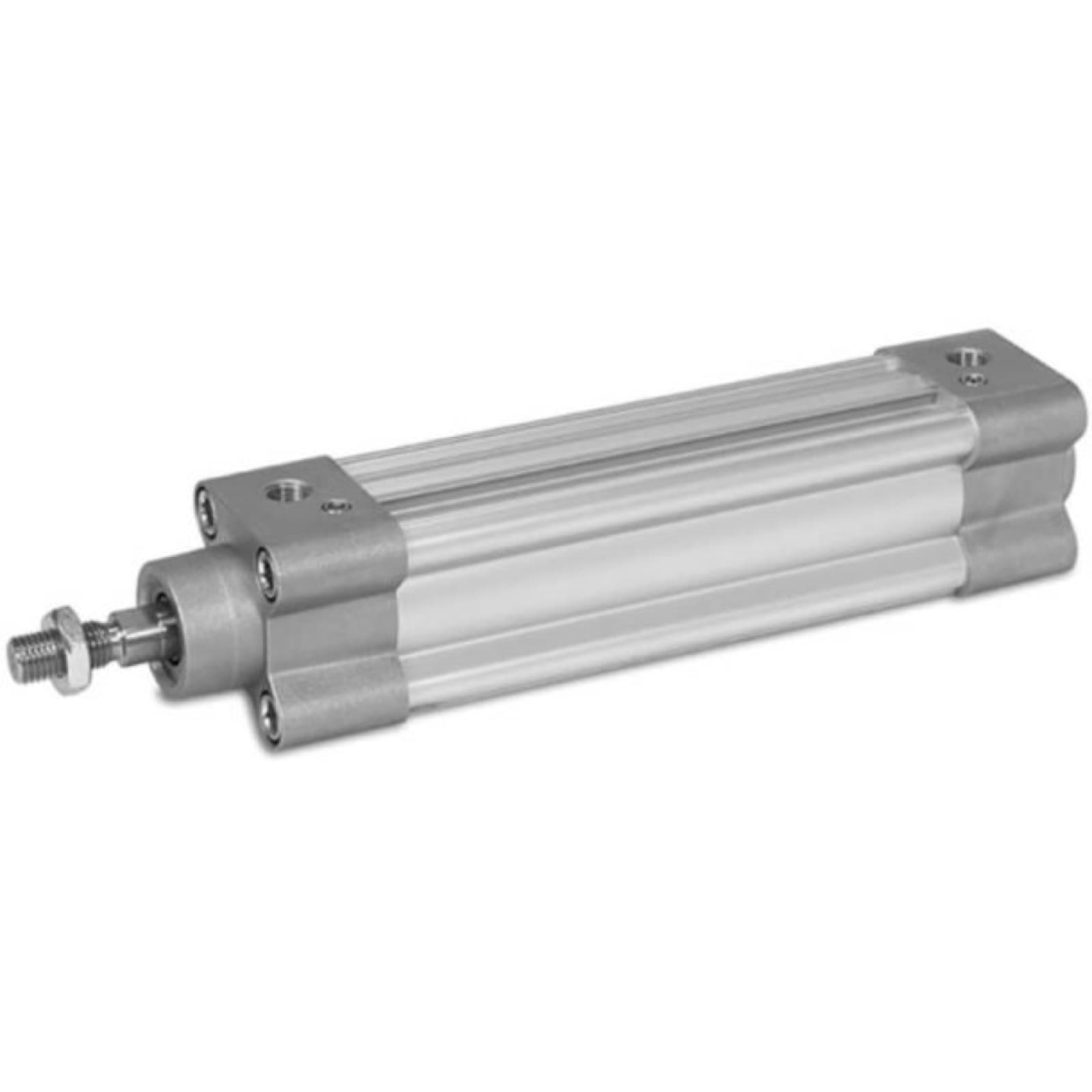 IH-PAR-P1F-SERIES-TIE-ROD-PNEUMATIC-CYLINDERS-SMOOTH-7Parker P1F Series Tie Rod Pneumatic Cylinders, Smooth Profile, 80mm BoreParker Hannifin
- IH-PAR-P1F-SERIES-TIE-ROD-PNEUMATIC-CYLINDERS-SMOOTH-5Parker P1F Series Tie Rod Pneumatic Cylinders, Smooth Profile, 50mm BoreParker Hannifin
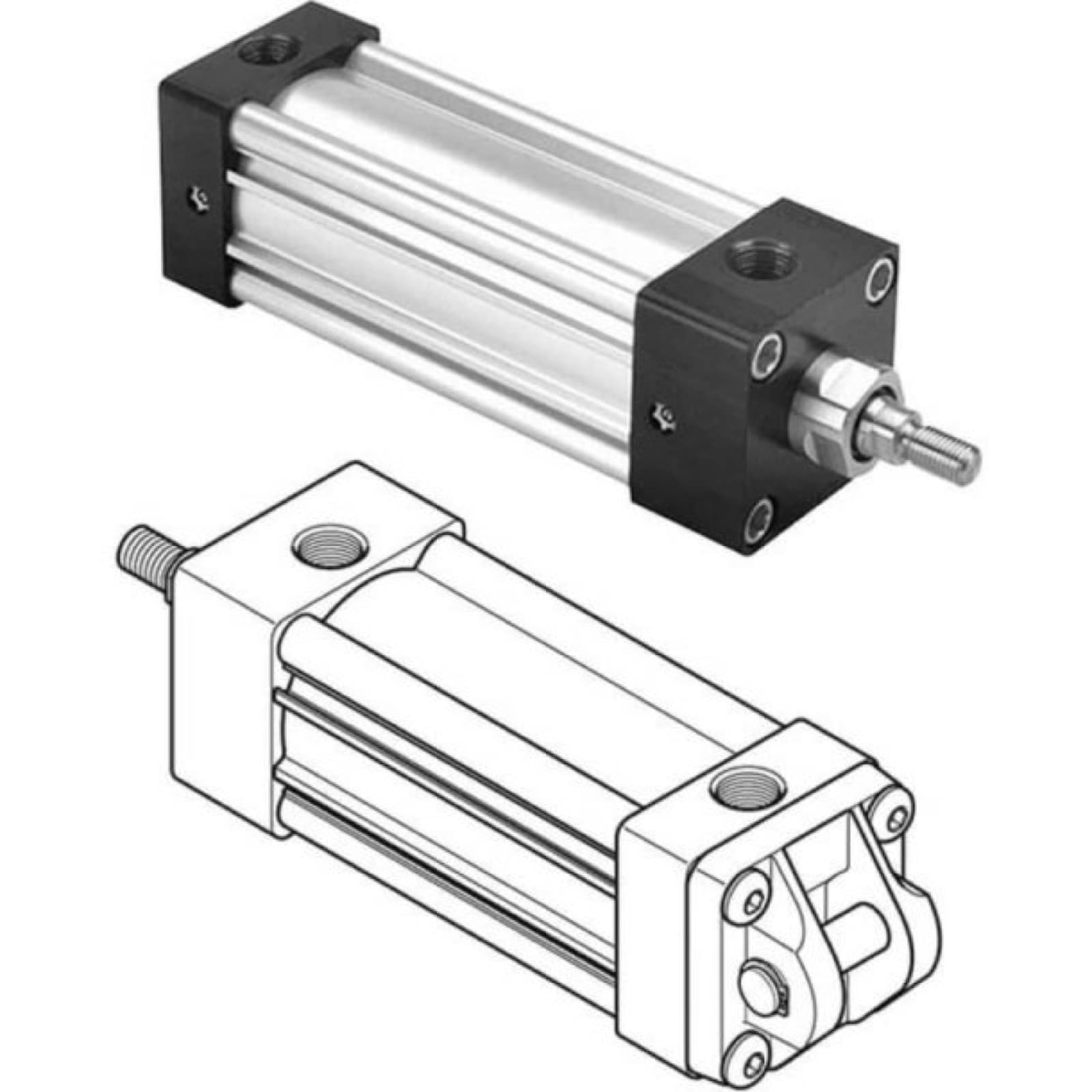 IH-PAR-4MA-SERIES-TIE-ROD-PNEUMATIC-CYLINDERS-2-1-2-INCHParker 4MA Series Tie Rod Pneumatic Cylinders, 2-1/2 Inch BoreParker Hannifin
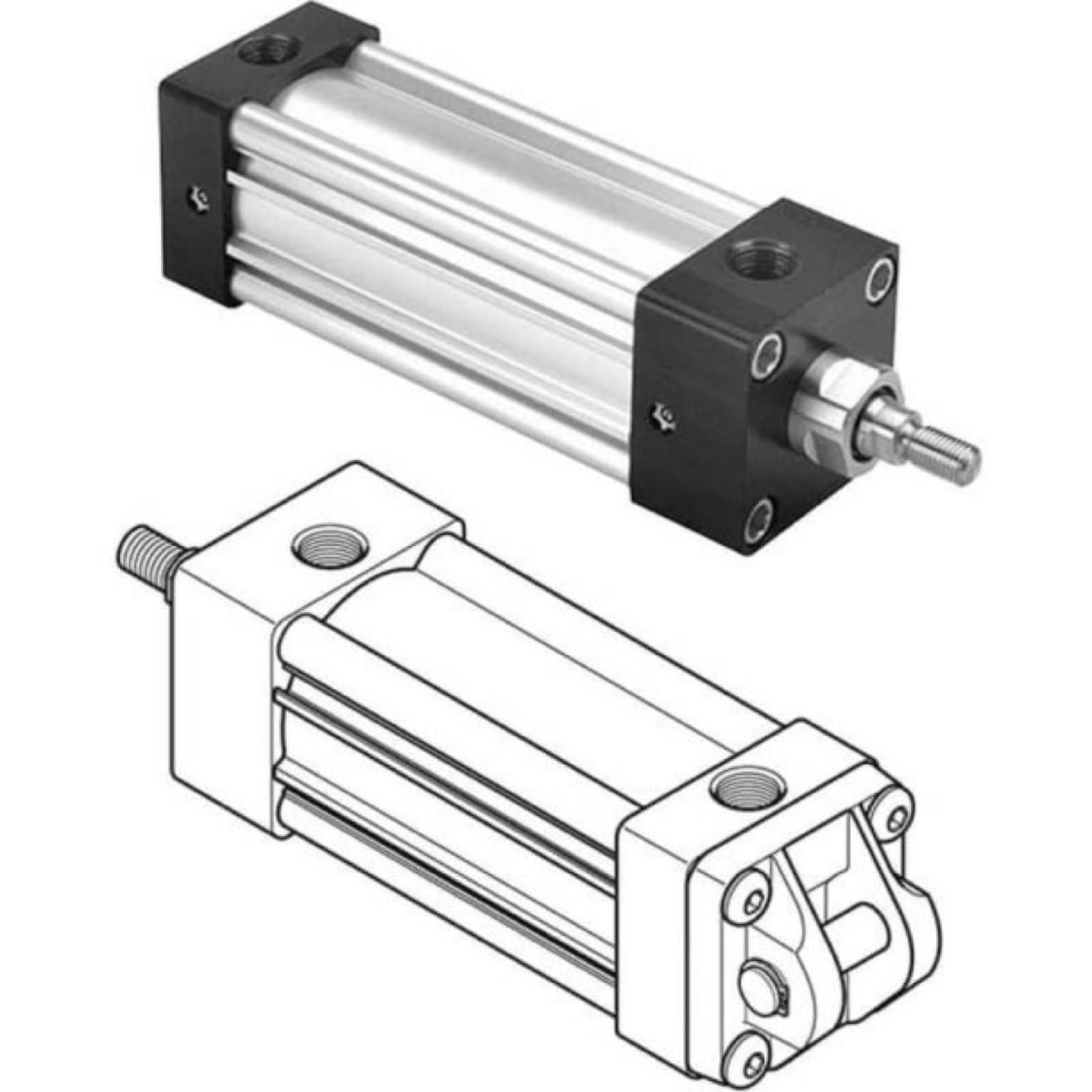 IH-PAR-4MA-SERIES-TIE-ROD-PNEUMATIC-CYLINDERS-3-1-4-INCHParker 4MA Series Tie Rod Pneumatic Cylinders, 3-1/4 Inch BoreParker Hannifin
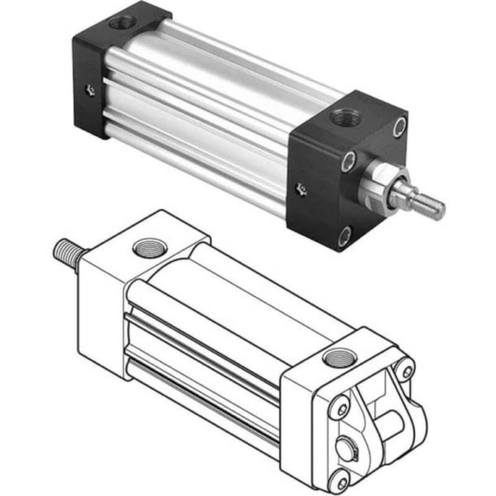 IH-PAR-4MA-SERIES-TIE-ROD-PNEUMATIC-CYLINDERS-2-INCH-BORParker 4MA Series Tie Rod Pneumatic Cylinders, 2 Inch BoreParker Hannifin
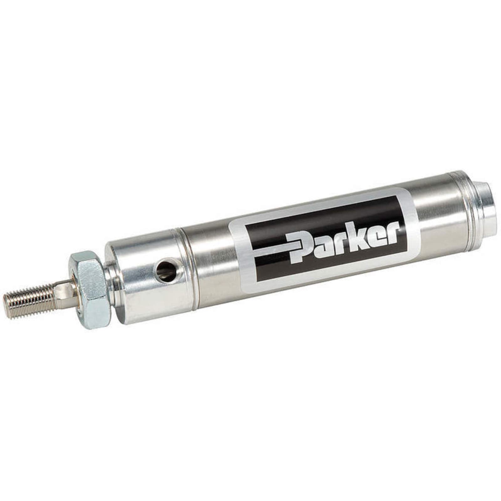 IH-PAR-SR-SERIES-AIR-CYLINDERS-2-INCH-BOREParker SR Series Air Cylinders, 2-Inch BoreParker Hannifin
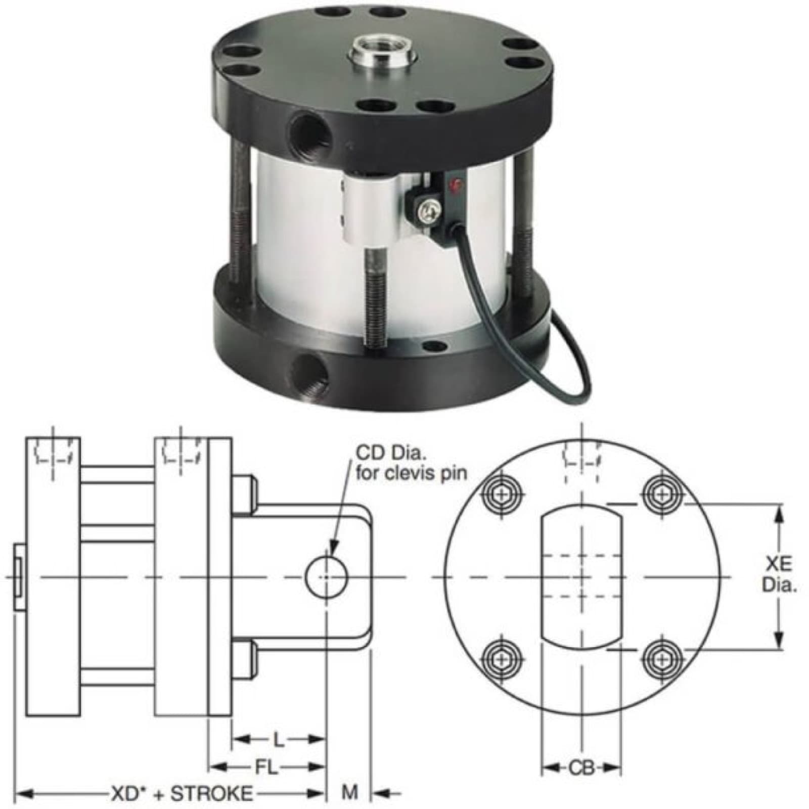 IH-PAR-LP-SERIES-COMPACT-PNEUMATIC-CYLINDERS-2-INCH-BOREParker LP Series Compact Pneumatic Cylinders, 2 Inch BoreParker Hannifin