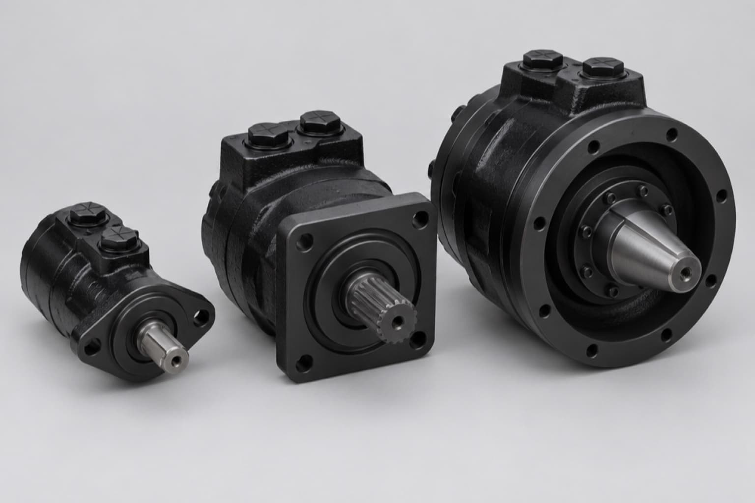
Orbital motors are the default drive for anything that turns slowly and needs to push hard: augers, conveyors, sweeper brushes, mixer drums, wheel drives on compact machines, winches and slew drives. They are also the motors most often replaced on the strength of a part number nobody can read any more. This guide explains how they work, how the families line up across makers, and how to identify one from the flange, shaft and ports.
/01How an orbital motor works.
Inside the motor is an internal gear set. A ring with internal lobes is fixed to the housing; inside it sits a star (rotor) with one tooth fewer. Oil pressure in the chambers between them pushes the star round — but because it has one tooth fewer, it does not simply rotate: its centre orbits inside the ring while it turns slowly on its own axis. A drive shaft with splines at both ends (the cardan or dogbone) connects the wobbling star to the output shaft. Every revolution of the output shaft involves many fillings and emptyings of the chambers — for a 6-tooth star in a 7-lobe ring, 42 cycles per revolution — which is why the motor produces high torque at low speed from a small body.
A distributor valve, driven in step with the star, connects each chamber to the inlet or the outlet at the right moment. Reverse the flow and the motor reverses.
Gerotor and geroler
In a plain gerotor set, the star’s teeth slide against the ring’s lobes. In a geroler (roller) set, the ring carries rollers that the star rolls against, giving lower friction, higher mechanical efficiency and better starting torque. Char-Lynn uses geroler sets with precision rollers across its range; Danfoss’s OMS, OMT and OMV have roller gear rims.
Spool valve and disc valve
In a spool-valve motor, the distributor is machined into the output shaft itself, turning in the housing. It is compact and economical. In a disc-valve motor, the distributor is a separate disc driven by a short second cardan (the valve drive), with a balance plate countering the hydraulic forces on it. Separating the valve from the output shaft means side load on the shaft no longer disturbs the valve, and the output shaft can run in tapered roller bearings. Danfoss describes its disc-valve OMT and OMV as suited to continuous duty in rough conditions — high pressure, thin oil, frequent reversals — with good starting characteristics. Char-Lynn’s H, S and T series are spool-valve; the 2000, 4000, 6000 and 10000 series are disc-valve.
/02The Danfoss OM families.
| Family | Displacements (cc/rev) | Δp cont / int / peak (bar) | Notes |
|---|---|---|---|
| OML | 8–32 | 70 / 125 / 140 | Smallest; light duty |
| OMM | 8.2–50 | 100 / 140 / 200 on 8–20 cc; less on larger | Compact; small fans, pumps, conveyors |
| OMP | 25–389 | 100–140 / 140–175 / 225, falling on largest | General purpose |
| OMRHighlighted | 51.6–373 | 175 / 200 / 225 on 80–125 cc; falling on largest | Most common general-purpose size |
| OMH | 201–471 | 175 / 200 / 225 on 200–250 cc | Heavier shaft and bearings |
| OMS | 80.5–488 | 210 / 275 / 295 on 80–125 cc | Roller set; tapered bearings on wheel versions |
| OMT | 161–524 | 200 / 240 / 280 on 160–315 cc | Disc valve, roller rim, tapered bearings |
| OMV | 315–802 | 200 / 240 / 280 on 315–500 cc | Largest; up to 1,880 Nm continuous |
Two rules run through every Danfoss table. Intermittent ratings apply to no more than 10% of every minute and peak ratings to no more than 1%. And within each family, pressure ratings fall as displacement rises — the largest OMR is rated only 55 bar continuous on its standard shaft — while the shaft itself often limits torque before the gear set does: an OMS on a 7/8" spline is limited to 200 Nm regardless of size.
/03Char-Lynn series and part-number prefixes.
| Prefix | Series | Valve | Pressure | Torque | Flow |
|---|---|---|---|---|---|
| 101- | H | Spool | 141 / 177 bar (2,050 / 2,565 psi) | 407 / 520 Nm | 61 / 76 L/min |
| 103- | S | Spool, geroler | 135 / 170 bar (2,000 / 2,500 psi) | 465 / 530 Nm | 55 / 75 L/min |
| 104-, 106-Highlighted | 2000 | Disc | 205 / 310 bar (3,000 / 4,500 psi) | 845 / 930 Nm | 75 / 115 L/min |
| 109- | 4000 | Disc | 207 / 310 bar | 972 / 1,181 Nm | 95 / 151 L/min |
| 112- | 6000 | Disc, geroler | 200 / 300 bar | 1,685 / 1,875 Nm | 150 / 225 L/min |
| 119- | 10000 | Disc, geroler | 205 / 275 bar | 2,700 / 3,440 Nm | 170 / 265 L/min |
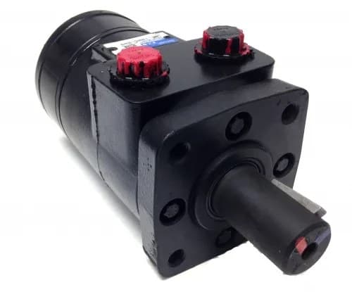
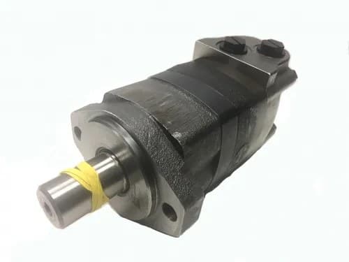
The first three digits of a Char-Lynn part number name the series, which is the fastest way to identify a motor whose tag is half gone: a 104-xxxx-006 is a 2000 series disc-valve motor, a 101- is an H series spool motor. The figures above are Danfoss’s own; some resellers quote the intermittent figure as continuous (310 bar “continuous” for the 2000 series is wrong — it is 205 bar continuous). The 2000 series is also built as a two-speed motor that switches displacement in a 1:2 ratio: roughly half the torque at about double the speed in high-speed mode.
We list Char-Lynn 101 (2.8–22.6 in³/rev), 103 (4.6–22.7 in³/rev), 104 (4.9–18.7 in³/rev) and 112/119 motors (19.0–30.0 in³/rev) part number by part number, with the mount, shaft and port of each.
/04What the BM codes mean.
Replacement orbital motors from Asian makers are usually coded BM followed by a letter: BMM, BMP, BMR, BMH, BMS, BMT, BMV. The letter follows the Danfoss family it is patterned on — BMR for OMR, BMS for OMS, BMV for OMV — and the published displacement ranges line up: BMM 8–50 cc against OMM 8–50, BMR 50–375 against OMR 50–375, BMV 315–800 against OMV 315–800. Suffixes such as BMPH, BMRS and BMSY denote variants within the pattern (heavier bearings, side ports, wheel mounts and so on, depending on the maker).
Our DFC listings follow the same codes, with displacement and both continuous and intermittent ratings per part number: BMM(Z) 8.2–50.3 cc; BMPH 36–390 cc; BMRS 51.7–381.4 cc; BMH 203–489 cc; BMSY wheel motors 81–475 cc; BMT 161–802 cc; BMV 333–990 cc; and the large BMK6 (196–982 cc on an SAE CC flange) and BMER wheel motors (118–745 cc).
/05Flanges, shafts and ports.
| Mount | Pilot diameter | Bolt circle / holes | Typical use |
|---|---|---|---|
| SAE A 2-boltHighlighted | 82.55 mm (3.25") | 106.4 mm, Ø13.5 holes | General purpose: augers, conveyors |
| SAE A 4-bolt (oval or square) | 82.55 mm | 4 holes | Where a stiffer mount is wanted |
| Char-Lynn 4-bolt square (H, S) | 44.4 mm (1.75") | 82.6 mm (3.25"), 3/8-16 tapped | Older Char-Lynn installs |
| SAE B 2-bolt | 101.6 mm (4.00") | 146.0 mm (5.75") | Larger motors, 2000 series |
| SAE B 4-bolt | 101.6 mm | 127.0 mm (5.00") | 4000 series and similar |
| SAE C 4-bolt | 127.0 mm (5.00") | 161.9 mm (6.38") | Large motors: 10000, OMV |
| Wheel mount | Recessed flange | Per maker | Wheels, drums: load between bearings |
| Bearingless (short) | — | Mounts into the gearbox | Gearbox and wheel drives that carry the load |
“Magneto” mount is a trade name used by several makers — Danfoss and Parker both offer one — for a small square or diamond flange; its dimensions are not standardised across makers, so measure the pilot and bolt pattern rather than trusting the name. A wheel mount has its flange recessed toward the middle of the motor so that a wheel hub or drum carries its load between the two bearings, which is what lets a wheel motor carry the machine’s weight.
Shafts
- Straight keyed: 1" and 1-1/4" (SAE key), 25 mm and 32 mm (DIN 6885 keys), 40 mm on large frames.
- Splined: 1" SAE 6B straight-sided; 7/8" 13-tooth 16/32 pitch; 1-1/4" 14-tooth 12/24 pitch involute; 1-1/2" 17-tooth; 2-1/8" 16-tooth on the largest motors.
- Tapered with nut: 1-1/4" taper is common on wheel motors; 35 mm 1:10 on European frames.
Ports
7/8-14 UNF SAE O-ring boss on most US-pattern motors (1-1/16-12 and 1-5/16-12 on larger frames), 1/2" NPTF on older Char-Lynn and some OMR, G 1/2 BSPP on European motors, M22×1.5 ISO 6149 on some, and manifold ports for valve blocks. Drain ports are usually 7/16-20 UNF or G 1/4.
/06Case drains, brakes and circuits.
Danfoss motors (except the OMEW) are three-chamber designs that isolate high pressure from the case, so an external drain can be fitted when return pressure is too high for the shaft seal. Whether it is needed depends on the plumbing: with internal check valves and no drain, the seal sees return pressure; with neither checks nor drain, it sees the average of inlet and return. Seal limits also fall with speed. Fit a drain, straight to tank, on series circuits, on restricted returns, on every brake motor and on any bearingless motor built into a gearbox. Danfoss’s high-pressure shaft seal option makes a drain unnecessary in most conditions.
Brakes: an orbital motor cannot hold a load — Danfoss is explicit that internal leakage will let it move. Winches, slew drives and wheel drives on slopes need a holding brake, integral or external; brake motors such as the OMR F and OMT FX/FL/FH are parking brakes, released by pressure.
Series or parallel: in series, every motor runs at the same speed and pressure splits between them, so the first motor must be rated for the full inlet pressure and each for its back pressure. In parallel, every motor sees full pressure and flow divides by load — if one wheel loses grip it takes all the flow and the others stop, so fit a flow divider.
Overrunning loads turn the motor into a pump. Control them with a counterbalance or brake valve, and keep positive pressure on the low side so the gear set does not cavitate while braking.
/07Oil, run-in and what wears them out.
- Cleanliness: Danfoss asks for ISO 4406 20/16 or better, achieved with a return filter finer than 40 µm absolute, and 20 µm absolute in dirty or complex systems. Fit a pressure filter ahead of the motor where quick couplers are used.
- Temperature: Danfoss gives 30–60 °C as normal oil temperature and notes that oil life halves for every 8 °C above 60 °C — a figure worth remembering on any Gulf machine whose tank runs hotter than that.
- Viscosity: 20–75 mm²/s at running temperature, 35 mm²/s recommended; HLP or HM anti-wear mineral oil.
- Run-in: fill through a fine filter, bleed, and run unloaded for 15–30 minutes before putting load on. Foam, jerky motion or noise means air is still in the circuit.
- Installation: flat mounting faces in full contact; never pull the motor into place with its bolts; no PTFE tape on threads; port plugs left in until the hoses go on.
- Side load: sprockets, pulleys and wheels load the bearings — side load is torque divided by the sprocket radius. Tapered-roller motors (OMT, OMV, wheel versions, Char-Lynn 2000) carry far more than slide-bearing designs, and halving speed doubles bearing life.
Identifying an orbital motor for replacement
IfIs there a readable part number?
Char-Lynn: the first three digits name the series. Danfoss: OM + letter + displacement. BM-coded: the letter names the Danfoss pattern.
IfMeasure the flange
Pilot diameter and bolt circle: 82.55 mm = SAE A, 101.6 mm = SAE B, 127 mm = SAE C; 44.4 mm pilot on a 4-bolt square = older Char-Lynn.
IfMeasure the shaft
Diameter, keyed or splined (count teeth), or tapered.
IfIdentify the ports
Thread (7/8-14 UNF, 1/2 NPTF, G 1/2) and whether they are side, end or manifold.
IfFind the displacement
From the tag, or by measuring flow and speed: cc/rev = L/min × 1,000 ÷ rpm.
IfCheck the duty
Wheel or sprocket load, back pressure, brake — these decide between a standard, wheel, bearingless or brake motor.
Common questions
- What is an orbital hydraulic motor?
- A low-speed, high-torque motor built on an internal gear set — a star orbiting inside a lobed ring — with a valve that feeds each chamber in turn. It gives high torque at low speed from a small body.
- What is the difference between a gerotor and a geroler motor?
- In a gerotor the star’s teeth slide against the ring. In a geroler the ring carries rollers, which reduce friction and improve mechanical efficiency and starting torque.
- What is the difference between spool and disc valve orbital motors?
- A spool-valve motor has the distributor built into the output shaft — compact and economical. A disc-valve motor has a separate valve disc with its own drive, so it tolerates higher pressure, shaft side load and rough duty better.
- What does the Char-Lynn part number prefix mean?
- It names the series: 101 = H, 103 = S, 104 and 106 = 2000, 109 = 4000, 112 = 6000, 119 = 10000.
- Are BM motors interchangeable with Danfoss?
- The BM letter follows the Danfoss family — BMR for OMR, BMS for OMS — and the displacement ranges match. Confirm flange, pilot, shaft, ports and displacement against the motor you are replacing before ordering.
- Does an orbital motor need a case drain?
- When return pressure would exceed the shaft seal’s limit — series circuits, restricted returns — and always on brake motors and bearingless motors in gearboxes. Many run without one on simple circuits.
- Can an orbital motor hold a load?
- No. Internal leakage lets the load move. Use an integral or external holding brake on winches, slew drives and wheel drives.
- What is a magneto mount?
- A trade name for a small square or diamond flange used by several makers. It is not a single standard, so measure the pilot and bolt pattern.
What we list
Every orbital motor in the range:
- Char-Lynn 101 Series Hydraulic Motors
- Char-Lynn 103 Series (S Series) Hydraulic Motors
- Char-Lynn 104 Series Hydraulic Motors
- Char-Lynn 112 and 119 Series Hydraulic Motors
- Dynamic Fluid Components BMER Orbital Motors, Magneto Mount, 1" Keyed Shaft
- Dynamic Fluid Components BMER Orbital Motors, Magneto Mount, 1 1/4" Keyed Shaft
- Dynamic Fluid Components BMER Orbital Motors, Magneto Mount, Splined Shaft
- Dynamic Fluid Components BMER Orbital Motors, Magneto Mount, 1 1/4" Tapered Shaft
- Dynamic Fluid Components BMER Orbital Motors, Wheel Mount
- Dynamic Fluid Components BMH Orbital Motors
- Dynamic Fluid Components BMK6 Orbital Motors
- Dynamic Fluid Components BMM(Z) Orbital Motors
- Dynamic Fluid Components BMPH Orbital Motors, 2-Bolt SAE A Mount
- Dynamic Fluid Components BMPH Orbital Motors, 4-Bolt Mount
- Dynamic Fluid Components BMPH Orbital Motors, Magneto Mount
- Dynamic Fluid Components BMRS Orbital Motors, 2-Bolt SAE A Mount
- Dynamic Fluid Components BMRS Orbital Motors, 4-Bolt Mount
- Dynamic Fluid Components BMRS Orbital Motors, Magneto Mount
- Dynamic Fluid Components BMSY Orbital Motors, 2-Bolt SAE A Mount
- Dynamic Fluid Components BMSY Orbital Motors, 4-Bolt Mount
- Dynamic Fluid Components BMSY Orbital Motors, Magneto Mount
- Dynamic Fluid Components BMSY Orbital Motors, Wheel Mount
- Dynamic Fluid Components BMT Orbital Motors
- Dynamic Fluid Components BMV Orbital Motors
- Fluidyne 500 Series Orbital Motors, 6-Bolt Magneto Mount
- Fluidyne 500 Series Orbital Motors, Wheel Mount
- Fluidyne 501 Series Orbital Motors, 6-Bolt Magneto Mount
- Fluidyne 501 Series Orbital Motors, Wheel Mount
- Fluidyne FM1 Series Orbital Motors, 2-Bolt SAE A Mount
- Fluidyne FM1 Series Orbital Motors, 4-Bolt SAE A Square Mount
- Fluidyne FM3 Series Orbital Motors, 2-Bolt SAE A Mount
- Fluidyne FM3 Series Orbital Motors, 4-Bolt SAE A Square Mount
- Fluidyne FM50 Series Orbital Motors, 6-Bolt Magneto Mount
- Fluidyne FM50 Series Orbital Motors, Wheel Mount
- Fluidyne FM51 Series Orbital Motors, 6-Bolt Magneto Mount
- Fluidyne FM51 Series Orbital Motors, Wheel Mount
- Fluidyne WF101 Series Orbital Motors, 2-Bolt SAE A Mount
- Fluidyne WF101 Series Orbital Motors, 4-Bolt SAE A Square Mount
- Fluidyne WF101 Series Orbital Motors, 4-Bolt Magneto (SAE A) Mount
- Fluidyne WF103 Series Orbital Motors, 2-Bolt SAE A Mount
- Fluidyne WF103 Series Orbital Motors, 4-Bolt SAE A Square Mount
- Fluidyne WF103 Series Orbital Motors, 4-Bolt Magneto (SAE A) Mount
- Fluidyne WF104 Series Orbital Motors, 2-Bolt SAE A Mount
- Fluidyne WF104 Series Orbital Motors, 2-Bolt SAE B Mount
- Fluidyne WF104 Series Orbital Motors, 4-Bolt SAE A Square Mount
- Fluidyne WF104 Series Orbital Motors, 4-Bolt Magneto Mount
- Fluidyne WF104 Series Orbital Motors, 4-Bolt Magneto (SAE A) Mount
- Fluidyne WF104 Series Orbital Motors
- Fluidyne WF105 Series Orbital Motors, Wheel Mount
- Fluidyne WF106 Series Orbital Motors, 4-Bolt Mount
- Fluidyne WF109 Series Orbital Motors, 4-Bolt SAE B Mount
- Fluidyne WF109 Series Orbital Motors, 4-Bolt SAE C Mount
- Fluidyne WF112 Series Orbital Motors, 4-Bolt Mount
- Fluidyne WF112 Series Orbital Motors, 4-Bolt SAE C Mount
- Fluidyne WF113 Series Orbital Motors, Wheel Mount
- Fluidyne WF114 Series Orbital Motors, 4-Bolt SAE C Bearingless Mount
- Fluidyne WF119 Series Orbital Motors, 4-Bolt SAE C Mount
- Fluidyne WF129 Series Orbital Motors, 2-Bolt Mount
- Fluidyne WF129 Series Orbital Motors, 3-Bolt Mount
- Fluidyne WF129 Series Orbital Motors, 3-Bolt / 5-Bolt Mount
- Fluidyne WF129 Series Orbital Motors
- Fluidyne WF130 Series Orbital Motors
Orbital motors by frame
- IH-DFC-BMMZDynamic Fluid Components BMM(Z) Orbital MotorsDynamic Fluid Components
- IH-DFC-BMPH-2BADynamic Fluid Components BMPH Orbital Motors, 2-Bolt SAE A MountDynamic Fluid Components
- IH-DFC-BMRS-4BDynamic Fluid Components BMRS Orbital Motors, 4-Bolt MountDynamic Fluid Components
- IH-DFC-BMTDynamic Fluid Components BMT Orbital MotorsDynamic Fluid Components
- IH-DFC-BMVDynamic Fluid Components BMV Orbital MotorsDynamic Fluid Components
 IH-CL-101Char-Lynn 101 Series Hydraulic MotorsChar-Lynn
 IH-CL-104Char-Lynn 104 Series Hydraulic MotorsChar-Lynn
- IH-FLD-WF105-WHLFluidyne WF105 Series Orbital Motors, Wheel MountFluidyne
Each listing gives displacement, mount, shaft, ports and continuous and intermittent ratings per part number.
Orbital Motors — General technical information (BC152886483554en-000401)
Danfoss’s own explanation of orbital-motor construction, duty definitions, efficiency, shaft-seal plumbing, brakes and oil requirements, used throughout this article.