Most cylinder sizing mistakes are not arithmetic mistakes. The formula is one line long. They are mistakes about which pressure, which area and which length: the relief setting used instead of the pressure at the port, the full bore used for a pulling job, the stroke used instead of the length that actually buckles. This guide works through each of those with real numbers, in both inch and metric units, and ends with the checks worth making before an order goes in.
/01Force is pressure times area.
A hydraulic cylinder is a force multiplier with one rule: every square inch of piston exposed to oil at a given pressure pushes with that pressure. So the force a cylinder produces is the pressure behind the piston multiplied by the area it acts on.
- Imperial: force (lbf) = pressure (psi) × area (in²), where area = π × bore² ÷ 4.
- Metric: force (kN) = pressure (bar) × area (cm²) ÷ 100, where area = π × bore² ÷ 4 with the bore in centimetres.
A 3" bore has an area of 7.069 in². At 3,000 psi that is 21,206 lbf — a little over 9.6 tonnes of push. A 100 mm bore has 78.54 cm²; at 160 bar it pushes 125.7 kN, which is the figure printed on the Rexroth CDT3 100/70 tie-rod cylinder we stock.
Force rises with the square of the bore. Going from a 3" to a 4" bore is a 33% larger diameter but a 78% larger area, so the same pressure pushes 78% harder. That is why bore steps of half an inch matter more at the top of the range than at the bottom.
/02The rod side is smaller, so pulling is weaker.
On the retract stroke, oil enters the rod end and pushes on the ring of piston left around the rod — the annulus. Its area is the bore area minus the rod area. For the 3" bore with a 1.5" rod, that is 7.069 − 1.767 = 5.301 in², so at 3,000 psi it pulls 15,904 lbf: exactly three quarters of the push.
The ratio of the two areas is worth knowing for every cylinder on a machine, because it governs three separate things — pull force, retract speed and how much oil comes back out of the cap end. It is usually written as φ (phi) in European catalogues. Typical values:
- 1.5" bore, 1" rod: 1.80
- 2" bore, 1.25" rod: 1.64
- 3" bore, 1.5" rod: 1.33
- 4" bore, 1.75" rod: 1.24
- 100 mm bore, 56 mm rod: 1.46; 100 mm bore, 70 mm rod: 1.96
If the job is pulling — a tensioner, a hitch, a door that is drawn shut — size from the annulus, not the bore. It is the commonest single error we see on enquiries: a cylinder sized correctly for push and fitted the wrong way round.
| Bore × rod | Bore area (in²) | Push @ 2,500 psi (lbf) | Push @ 3,000 psi (lbf) | Pull @ 3,000 psi (lbf) | Area ratio |
|---|---|---|---|---|---|
| 1.5" × 1" | 1.767 | 4,418 | 5,301 | 2,945 | 1.80 |
| 2" × 1.25" | 3.142 | 7,854 | 9,425 | 5,743 | 1.64 |
| 2.5" × 1.25" | 4.909 | 12,272 | 14,726 | 11,045 | 1.33 |
| 3" × 1.5"Highlighted | 7.069 | 17,671 | 21,206 | 15,904 | 1.33 |
| 3.5" × 1.75" | 9.621 | 24,053 | 28,863 | 21,648 | 1.33 |
| 4" × 1.75" | 12.566 | 31,416 | 37,699 | 30,483 | 1.24 |
| 5" × 2" | 19.635 | 49,087 | 58,905 | 49,480 | 1.19 |
| 6" × 2.5" | 28.274 | 70,686 | 84,823 | 70,097 | 1.21 |
| 8" × 3" | 50.265 | 125,664 | 150,796 | 129,591 | 1.16 |
| Bore / rod (mm) | Bore area (cm²) | Push @ 160 bar (kN) | Push @ 250 bar (kN) | Pull @ 250 bar (kN) | Area ratio |
|---|---|---|---|---|---|
| 40 / 22 | 12.57 | 20.1 | 31.4 | 21.9 | 1.43 |
| 50 / 28 | 19.63 | 31.4 | 49.1 | 33.7 | 1.46 |
| 63 / 36 | 31.17 | 49.9 | 77.9 | 52.5 | 1.48 |
| 80 / 45 | 50.27 | 80.4 | 125.7 | 85.9 | 1.46 |
| 100 / 56Highlighted | 78.54 | 125.7 | 196.3 | 134.8 | 1.46 |
| 125 / 70 | 122.72 | 196.3 | 306.8 | 210.6 | 1.46 |
| 160 / 90 | 201.06 | 321.7 | 502.7 | 343.6 | 1.46 |
| 200 / 110 | 314.16 | 502.7 | 785.4 | 547.8 | 1.43 |
/03Speed is flow divided by area.
Pressure sets force; flow sets speed. The piston moves exactly as fast as the oil arriving behind it can fill the space it leaves:
- Imperial: speed (in/min) = flow (gpm) × 231 ÷ area (in²). Divide by 60 for in/s.
- Metric: speed (m/min) = flow (L/min) × 10 ÷ area (cm²). For mm/s, multiply by 1,000 and divide by 60.
A 3" bore fed 10 gpm extends at 10 × 231 ÷ 7.069 = 327 in/min, or 5.4 in/s. A 24" stroke therefore takes about 4.4 seconds. On the return stroke the same 10 gpm fills only the 5.301 in² annulus, so the rod comes back at 7.3 in/s and the stroke takes 3.3 seconds.
Metric: a 100 mm bore, 56 mm rod cylinder fed 40 L/min extends at 85 mm/s and retracts at 124 mm/s.
The return flow is bigger than the supply
On the retract stroke, the cap end empties a larger volume than the rod end receives. The oil leaving the cap end is the supply flow multiplied by the area ratio: 10 gpm in, 13.3 gpm out on the 3" × 1.5" cylinder; on a 2" × 1.25" cylinder, 16.4 gpm out. That figure — not the pump flow — is what the return line, the directional valve’s tank path and the return filter have to pass. An undersized return filter on a large-rod cylinder goes into bypass on every retract stroke, and nobody notices until the pump starts to wear.
| Bore | Extend, in/s per gpm | At 10 gpm, in/s | At 20 gpm, in/s |
|---|---|---|---|
| 1.5" | 2.18 | 21.8 | 43.6 |
| 2" | 1.23 | 12.3 | 24.5 |
| 2.5" | 0.78 | 7.8 | 15.7 |
| 3"Highlighted | 0.54 | 5.4 | 10.9 |
| 3.5" | 0.40 | 4.0 | 8.0 |
| 4" | 0.31 | 3.1 | 6.1 |
| 5" | 0.20 | 2.0 | 3.9 |
| 6" | 0.14 | 1.4 | 2.7 |
| 8" | 0.08 | 0.8 | 1.5 |
/04Choosing the bore: a worked example.
The job: lift a 12,000 lb load vertically, 24" of travel, on a machine with a 3,000 psi relief valve and an 11 gpm gear pump.
- Find the pressure that reaches the cylinder. The relief valve setting is a ceiling, not a working pressure. Between the pump and the cap port sit a directional valve, hoses, fittings and perhaps a flow control, each costing pressure. On a typical mobile circuit we would plan on 2,500 psi at the port, not 3,000.
- Add margin over the load. Seal friction, acceleration, a load that is not quite where the drawing says and pressure loss that grows as the oil warms all eat into the force. 20–25% over the static load is a sensible floor: 12,000 × 1.25 = 15,000 lbf.
- Solve for the area. 15,000 ÷ 2,500 = 6.0 in². The bore with at least that area is 3" (7.069 in²), which pushes 17,671 lbf at 2,500 psi. A 2.5" bore (4.909 in²) would lift 12,272 lbf at 2,500 psi — technically more than the load, but with 2% margin, which is no margin.
- Check the speed. 11 gpm into 7.069 in² is 6.0 in/s; 24" takes 4 seconds up. Retract with a 1.5" rod: 8.0 in/s.
- Check the rod. A 24" stroke with a 1.5" rod is nowhere near its buckling limit (section 6). If the stroke were 60", it would be.
Metric version: 80 kN of load with 25% margin is 100 kN; at 160 bar at the port that needs 62.5 cm², so a 100 mm bore (78.5 cm²) rather than an 80 mm (50.3 cm²).
Bore selection, step by step
Work through in order. Each step can change the answer of the one before.
IfIs the working stroke a push or a pull?
Push: size from the full bore area. Pull: size from the annulus (bore area minus rod area).
IfWhat pressure reaches the cylinder port?
Use the port pressure, not the relief setting. Allow for valve, hose and fitting losses — often 300–500 psi on a mobile circuit.
IfRequired area = (load × 1.25) ÷ port pressure
Pick the next standard bore up. If two bores are close, the larger buys margin and the smaller buys speed.
IfIs the speed acceptable at the pump’s flow?
Speed = flow × 231 ÷ area (in/min). Too slow: more flow, or a regenerative circuit for the light part of the stroke.
IfIs the stroke long, or the cylinder pivot-mounted at both ends?
Check rod buckling against the effective length. Long, slender, pin-to-pin cylinders are buckling-limited, not pressure-limited.
IfCan the rod end ever be blocked while the cap end is pressurised?
Check the intensified rod-end pressure against the cylinder rating (section 7).
/05Regenerative circuits: speed for free, force at a price.
In a regenerative circuit, the oil leaving the rod end on the extend stroke is routed back into the cap end instead of to tank. Both sides are then at the same pressure, and the net force is that pressure acting on the rod area alone. The cylinder behaves like a ram with the diameter of its rod.
- Speed = pump flow ÷ rod area. A 3" × 1.5" cylinder on 10 gpm extends at 21.8 in/s in regeneration, against 5.4 in/s normally — four times faster.
- Force = pressure × rod area. The same cylinder at 2,500 psi pushes 4,418 lbf instead of 17,671.
It is the right tool for a long approach stroke at low load — a press closing on a part, a ram running out to meet its work — usually switched out of regeneration by a pressure signal when the load arrives. It is the wrong tool for anything that needs force through the whole stroke. A cylinder with a rod exactly half the bore area (area ratio 2:1) extends and retracts at the same speed in regeneration, which is why some presses use 2:1 cylinders.
/06Long strokes: the rod buckles before the seals give up.
A cylinder pushing a load is a column, and a slender column fails by bowing sideways long before the steel is crushed. The classic model is Euler’s: the critical load is proportional to the rod’s stiffness (its diameter to the fourth power) and inversely proportional to the square of its effective length.
That has two consequences that surprise people:
- Length is punished twice. Double the effective length and the buckling load falls to a quarter. A 1.5" steel rod pinned at both ends over an effective length of 40" has a theoretical Euler load of about 46,000 lbf; at 80" it is about 11,500 lbf — before any safety factor.
- Rod size is rewarded four times. Going from a 1.5" to a 2" rod raises the buckling load by (2 ÷ 1.5)⁴ = 3.2 times, for a modest increase in weight.
You can see this in our own listings. The 3" Chief welded cross-tube cylinder is published with a column load of 21,200 lbs at short strokes — the full 3,000 psi push — falling to 3,210 lbs at a 60" stroke. Same bore, same rod, same pressure rating: the long one is limited by buckling, not by hydraulics. When a catalogue gives a column load, it is the number to use, not the push force.
Effective length depends on the mount
The length that buckles is not the stroke. It is the distance between the points that restrain the cylinder, adjusted for how they restrain it. A cylinder pinned at both ends (clevis to clevis, cross tube to cross tube) buckles over roughly its whole extended length. A cylinder rigidly mounted at the cap and guided at the rod end is far stiffer. Manufacturers publish a stroke factor for each mounting and rod-end condition — multiply the stroke by it to get the “basic length” used in their buckling charts. Pivot-to-pivot mounts carry the highest factors, which is exactly why long agricultural and loader cylinders run oversize rods.
Stop tubes
On long-stroke cylinders, makers fit a stop tube — a spacer on the rod behind the piston — so that at full extension the piston and gland are further apart. That spreads the bearing support and reduces the side load on both, which is what wears out a long cylinder that is otherwise correctly sized. The rule of thumb in trade guidance is that stop tubes are recommended above about 40" of stroke, with one inch of stop tube for every ten inches of stroke beyond 40": an 80" stroke gets a 4" stop tube, and the cylinder’s gross stroke becomes 84". Makers’ configurators work the same way — gross stroke equals working stroke plus stop tube. A stop tube reduces bearing wear and jack-knifing; it does not stop a rod that is too thin from bending, which only a larger rod does. Confirm against the maker’s chart for the mount you are using.
| Rod diameter | 40" effective length | 60" | 80" | 100" |
|---|---|---|---|---|
| 1" | 9,084 | 4,037 | 2,271 | 1,453 |
| 1.25" | 22,177 | 9,857 | 5,544 | 3,548 |
| 1.5"Highlighted | 45,987 | 20,439 | 11,497 | 7,358 |
| 1.75" | 85,197 | 37,865 | 21,299 | 13,631 |
| 2" | 145,342 | 64,596 | 36,335 | 23,255 |
/07Rod-end intensification: the pressure you did not set.
Pascal’s law works in both directions. If the cap end is pressurised and the oil in the rod end cannot escape, the piston is held in equilibrium by the trapped oil — and because the annulus is smaller than the bore, the trapped oil must be at a higher pressure to balance it. The rod-end pressure is the cap-end pressure multiplied by the area ratio.
- 3" × 1.5" cylinder, 3,000 psi on the cap: 4,000 psi in the rod end.
- 2" × 1.25": 4,923 psi.
- 2" × 1.5" (a heavy rod for its bore): 6,857 psi.
- Any cylinder with a 2:1 area ratio: 6,000 psi — double the supply.
Telescopic cylinders are worse: Parker warns that a blockage on the retract side of a double-acting telescopic can intensify pressure ten times or more, so 2,000 psi from the pump could trap 20,000 psi. Power & Motion has documented a gland blown out of a 2,500 psi cylinder for exactly this reason — on a cold morning, oil below its pour point had blocked the rod-side return.
This happens in ordinary circuits. A meter-out flow control that is closed down too far, a pilot-operated check that fails to open, a counterbalance valve set wrongly, a quick coupler on the return line that is not fully engaged — any of them can block the rod end while the pump pushes on the cap. The relief valve protects the pump side; nothing protects the rod side except the cylinder’s own rating. Rod seals extruding, gland retaining rings failing and rod-end hoses bursting on a circuit that “never sees more than 3,000 psi” are the usual evidence.
/08Before you order.
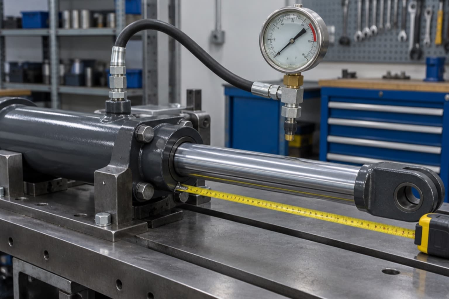
- Bore, rod and stroke — measure the barrel’s outside diameter and subtract twice the wall if you cannot see the bore; measure the rod with a caliper; measure stroke as the difference between closed and extended pin centres.
- Retracted (closed) length, pin centre to pin centre. A replacement with the right stroke but a longer closed length will not fit back between the pins.
- Mount at each end — clevis, cross tube, tang, pin eye, swivel eye — with pin diameter and, for a clevis, the gap width. See hydraulic cylinder mounting styles.
- Ports — SAE O-ring boss (ORB) size, NPT or BSPP, and their orientation.
- Working pressure at the cylinder, and whether the rod end can ever be blocked.
- Duty — cycles per hour, side load, temperature, and whether the rod is exposed to grit or salt spray.
Fluid power systems and components — Cylinder bores and piston rod diameters and area ratios — Metric series
Defines the preferred metric bore and rod diameters (32, 40, 50, 63, 80, 100, 125, 160, 200 mm bores and the rods that go with them) and the area ratios they produce. It is why metric cylinders from different makers share bore and rod sizes, and why the metric table above uses those pairs.
Common questions
- How do I calculate hydraulic cylinder force?
- Multiply the pressure by the area the oil acts on. Push: pressure × π × bore² ÷ 4. Pull: pressure × (bore area − rod area). In imperial units that gives pounds-force from psi and square inches; in metric, bar × cm² ÷ 100 gives kN.
- Why does my cylinder pull weaker than it pushes?
- Because on the retract stroke the oil acts only on the annulus around the rod, which is smaller than the full bore. A 3" bore with a 1.5" rod pulls 75% of what it pushes.
- Why does my cylinder retract faster than it extends?
- The same flow fills a smaller volume on the rod side, so the piston moves faster — by the area ratio. On a 3" × 1.5" cylinder it is a third faster.
- Should I size the cylinder for the relief valve pressure?
- No. Size it for the pressure that reaches the port after valve, hose and fitting losses, and leave 20–25% margin over the load. The relief valve is a ceiling for protection, not the working pressure.
- How long a stroke can a cylinder have?
- Until the rod buckles under the load. Buckling load falls with the square of the effective length, so long pin-to-pin cylinders need oversize rods and often a stop tube. Use the maker’s column load, which already includes a safety factor.
- What is pressure intensification in a cylinder?
- If the rod end is blocked while the cap end is pressurised, the rod-end pressure rises to the cap pressure multiplied by the area ratio — 4,000 psi from 3,000 psi on a 3" × 1.5" cylinder. It bursts rod seals and rod-end hoses.
- What is a regenerative cylinder circuit?
- A circuit that routes rod-end oil back into the cap end on the extend stroke. The cylinder extends at flow ÷ rod area — much faster — but pushes with only pressure × rod area.
- How much oil comes back out of the cylinder?
- On retract, the cap end returns the supply flow multiplied by the area ratio — 13.3 gpm for 10 gpm in on a 3" × 1.5" cylinder. Size the return line and filter for that, not for pump flow.
Cylinders by bore
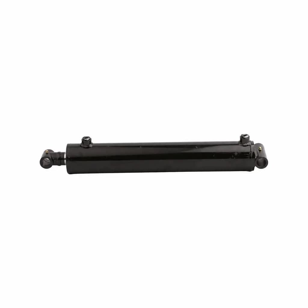 IH-CHF-CT-3Chief Welded Cross Tube Hydraulic Cylinder, 3" BoreChief
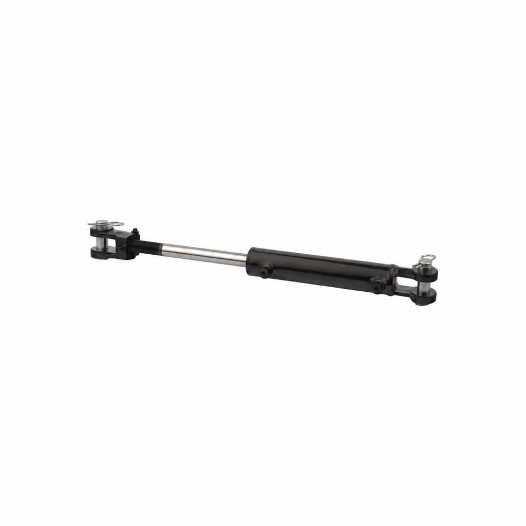 IH-MAX-CL-3Maxim Welded Clevis Hydraulic Cylinder, 3" BoreMaxim
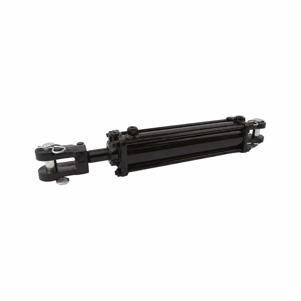 IH-CHF-TR-3Chief Tie-Rod Hydraulic Cylinder, 3" BoreChief
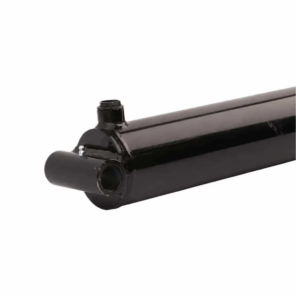 IH-MAG-WCTN-CT-4Magister WCTN Welded Cross Tube Hydraulic Cylinder, 4" BoreMagister Hydraulics
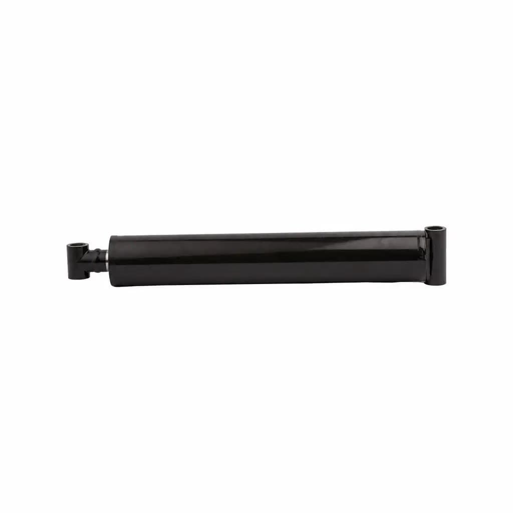 IH-BLY-CT-25Bailey Welded Cross Tube Hydraulic Cylinder, 2.5" BoreBailey International
- IH-CYL-100-70-500Rexroth CDT3 Tie-Rod Cylinder 100/70 × 500 mm, Foot Mounting MS2 (ISO 6020-2)Bosch Rexroth
Each listing gives bore, rod, stroke range and the column load for the stroke you pick.