
Wire rope clips are the one rope termination anyone can make with a spanner, which is exactly why so many of them are made wrong. A clip that is reversed, too few, under-tightened or never re-checked can let the rope slip or crush it at the point that carries the load. The rules fit on one page.
Which way round.
A U-bolt clip has two parts: the forged saddle, which cradles the rope, and the U-bolt, which clamps it. The U-bolt bites into the rope it sits on. So it goes on the dead end — the short tail after the rope has turned back around the thimble — and the saddle goes on the live end that carries the load.
Crosby’s instructions put it memorably: “Never saddle a dead horse.” The saddle belongs on the live rope. Every clip on the termination faces the same way; alternating them puts a U-bolt on the live rope at every other clip.
Fist grips are the exception. They have a saddle on both sides, so they grip the live and dead ends alike and cannot be fitted the wrong way round.
How many, and how tight: US-type clips.
The reference table for US-type drop-forged U-bolt clips is the one The Crosby Group publishes for its G-450 clip. It gives the minimum number of clips, the length of rope to turn back, and the nut torque, with threads clean, dry and unlubricated. If your clip maker publishes its own table, that one governs. The metric figures in brackets are our conversions.
| Clip size | Rope (mm) | Clips | Turnback | Torque |
|---|---|---|---|---|
| 1/8″ | 3–4 | 2 | 3-1/4″ (83 mm) | 4.5 ft-lb (6 N·m) |
| 3/16″ | 5 | 2 | 3-3/4″ (95 mm) | 7.5 ft-lb (10 N·m) |
| 1/4″ | 6–7 | 2 | 4-3/4″ (121 mm) | 15 ft-lb (20 N·m) |
| 5/16″ | 8 | 2 | 5-1/4″ (133 mm) | 30 ft-lb (41 N·m) |
| 3/8″ | 9–10 | 2 | 6-1/2″ (165 mm) | 45 ft-lb (61 N·m) |
| 7/16″ | 11–12 | 2 | 7″ (178 mm) | 65 ft-lb (88 N·m) |
| 1/2″ | 13 | 3 | 11-1/2″ (292 mm) | 65 ft-lb (88 N·m) |
| 9/16″ | 14–15 | 3 | 12″ (305 mm) | 95 ft-lb (129 N·m) |
| 5/8″ | 16 | 3 | 12″ (305 mm) | 95 ft-lb (129 N·m) |
| 3/4″ | 18–20 | 4 | 18″ (457 mm) | 130 ft-lb (176 N·m) |
| 7/8″ | 22 | 4 | 19″ (483 mm) | 225 ft-lb (305 N·m) |
| 1″ | 24–25 | 5 | 26″ (660 mm) | 225 ft-lb (305 N·m) |
| 1-1/8″ | 28–30 | 6 | 34″ (864 mm) | 225 ft-lb (305 N·m) |
| 1-1/4″ | 33–34 | 7 | 44″ (1118 mm) | 360 ft-lb (488 N·m) |
| 1-3/8″ | 36 | 7 | 44″ (1118 mm) | 360 ft-lb (488 N·m) |
| 1-1/2″ | 38–40 | 8 | 54″ (1372 mm) | 360 ft-lb (488 N·m) |
| 1-5/8″ | 41–42 | 8 | 58″ (1473 mm) | 430 ft-lb (583 N·m) |
| 1-3/4″ | 44–46 | 8 | 61″ (1549 mm) | 590 ft-lb (800 N·m) |
| 2″ | 48–52 | 8 | 71″ (1803 mm) | 750 ft-lb (1017 N·m) |
| 2-1/4″ | 56–58 | 8 | 73″ (1854 mm) | 750 ft-lb (1017 N·m) |
The table applies to regular-lay 6x19 and 6x37 class rope, fibre or steel core. Add one clip when a pulley or sheave takes the place of the thimble, and on Seale-construction 6x19 rope of 1″ and larger. If you use more clips than the table asks for, lengthen the turnback in proportion. For rope outside those constructions, ask the clip maker.
How many wire rope clips do I need?
It depends on the rope size, and the clip maker’s table sets the minimum. On the widely used US table: two clips up to 7/16″ rope, three for 1/2″ to 5/8″, four for 3/4″ and 7/8″, five for 1″, rising to eight from 1-1/2″. Add one if the rope turns around a sheave instead of a thimble.
DIN 1142 and EN 13411-5 grips.
Metric U-bolt grips of the DIN 1142 design are covered by EN 13411-5. Its table differs from the US one in two ways that matter: it specifies more grips on the smaller sizes, and its torques are for greased threads, not dry ones. Never mix the torque from one table with the thread condition of the other.
| Grip size (max rope) | Grips | Torque |
|---|---|---|
| 5 mm | 3 | 2.0 N·m |
| 6.5 mm | 3 | 3.5 N·m |
| 8 mm | 4 | 6.0 N·m |
| 10 mm | 4 | 9.0 N·m |
| 12 mm | 4 | 20 N·m |
| 14 mm | 4 | 33 N·m |
| 16 mm | 4 | 49 N·m |
| 19 mm | 4 | 68 N·m |
| 22 mm | 5 | 107 N·m |
| 26 mm | 5 | 147 N·m |
| 30 mm | 6 | 212 N·m |
| 34 mm | 6 | 296 N·m |
| 40 mm | 6 | 363 N·m |
For a rope between two sizes, use the next larger grip. EN 13411-5 places the first grip against the thimble with its bridge on the load-bearing rope, spaces the grips between 1.5 and 3 times the bridge width apart, and requires the termination to hold at least 80% of the rope’s minimum breaking force.
Terminations for steel wire ropes — Safety — Part 5: U-bolt wire rope grips
Specifies U-bolt wire rope grips, the number of grips and tightening torque by rope size, and a termination efficiency of at least 80% of the rope’s minimum breaking force. Its scope excludes grips as the main securing device on mine hoists, crane hoist ropes and the eyes of slings for general lifting service, and it does not cover spiral strand.
Making the termination.
- Turn back the length of rope given in the table and fit a thimble in the eye. The thimble stops the eye closing up and the rope bending sharply under load.
- Fit the first clip one base width from the end of the dead end, U-bolt on the dead end, saddle on the live end. Tighten to the table torque.
- Fit the next clip as close to the thimble as possible.
- Space any remaining clips equally between the first two.
- Take up the slack in the rope, then tighten every nut evenly, alternating from one nut to the other, to the table torque.
- Apply a first load at least equal to the load the termination will carry, then re-tighten every nut to the table torque.
- Inspect the termination and re-check the torque periodically in service.
Even a perfect clip termination is weaker than the rope. The US table’s maker rates it at 80% of the rope’s minimum breaking force for 1/8″ to 7/8″ clips and 90% from 1″ upward, and EN 13411-5 requires at least 80%. Work that reduction into the WLL before the eye goes on a hook — our guide to working load limit shows how.
The job clips must not do.
Clips must not be used to form the eyes of lifting slings. US federal rules for construction work say sling eyes “shall not be formed by wire rope clips or knots” (29 CFR 1926.251). EN 13411-5 excludes clips as the securing device on the eyes of slings for general lifting service, and the European wire rope sling standard, EN 13414-1, covers only ferrule-secured and spliced eyes.
US sling guidance allows a narrow exception — a sling designed by a qualified person where no prefabricated sling can be used — and even then requires drop-forged clips, never malleable ones, and never in a choker hitch. For almost every lift the answer is simpler: buy a ferrule-secured or spliced sling, rated and tagged by its maker.
Malleable iron clips — including the DIN 741 type and US-type malleable clips — are light-duty clamps. Crosby’s own guidance limits malleable cast-iron clips to non-critical applications. Use drop-forged clips wherever the termination carries a load that matters.
Which clip for the job
Start from what the termination holds.
If · A lifting sling eye
No clips. Use a ferrule-secured or spliced sling.
If · A guy, stay, fixed line or winch rope end
Drop-forged U-bolt clips or fist grips, installed to the maker’s table.
If · Metric rope on a European specification
DIN 1142 / EN 13411-5 grips, torqued on greased threads.
If · Marine or corrosive service
Stainless steel drop-forged or DIN 1142 grips, same installation rules.
If · Fencing, barriers, light non-critical ties
Malleable clips such as DIN 741 are acceptable here — and only here.
Clips and thimbles in this guide
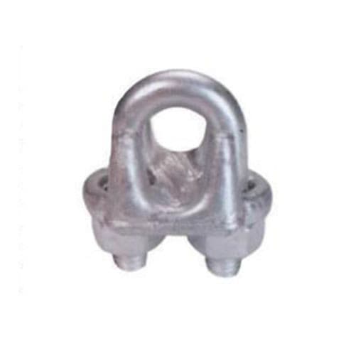
IH-LR-WC-DF
Drop Forged Wire Rope Clip — US Type, Hot-Dip Galvanized
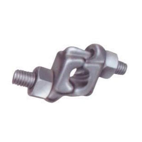
IH-LR-WC-FG
Drop Forged Fist Grip Wire Rope Clip, Hot-Dip Galvanized
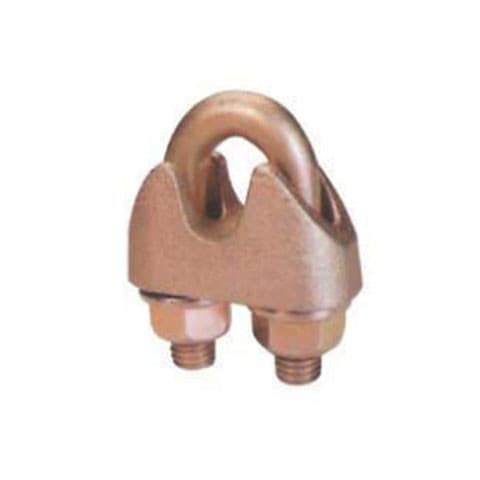
IH-LR-WC-D1142
DIN 1142 Wire Rope Clip — Yellow Chromated
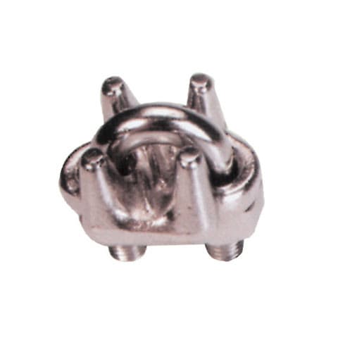
IH-LR-WC-SSDF
Stainless Steel Drop Forged Wire Rope Clip — US Type

IH-LR-WC-SSWRCD114
Stainless Steel Wire Rope Clip — DIN 1142 / EN 13411-5
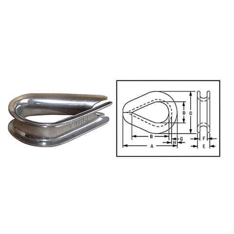
IH-LR-TH-US
Standard Wire Rope Thimble — G-411 Pattern
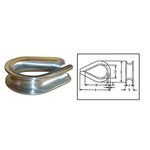
IH-LR-TH-EH
Extra Heavy Wire Rope Thimble — G-414 Pattern, Hot-Dip Galvanized
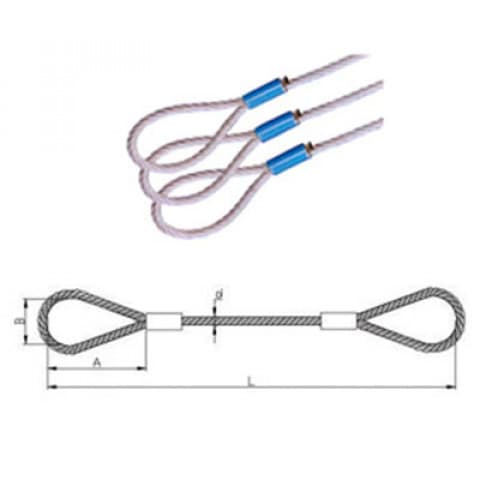
IH-LR-WS-SWG
Swaged Soft Eye Wire Rope Sling (Ferrule Secured)
Common questions
Which side of the rope does the U-bolt go on?
The dead end — the short tail. The saddle goes on the live end that carries the load. Every clip faces the same way. A clip with its U-bolt on the live rope crushes the load-bearing rope and weakens the termination.
How many clips for a 1/2 inch wire rope?
Three on the reference US table, with 11-1/2″ (292 mm) of rope turned back and 65 ft-lb (88 N·m) on dry threads. On a DIN 1142-style grip for 12 to 14 mm rope, EN 13411-5 asks for four.
Should the threads be greased before torquing?
Follow the table you are using. The US table’s torques are for clean, dry threads. EN 13411-5’s DIN 1142-style torques are for greased threads. Using one table’s torque with the other’s thread condition over- or under-tightens the clip.
Can I make a lifting sling with wire rope clips?
No. Sling eyes must not be formed with clips under US federal rules, EN 13411-5 excludes them for general-service sling eyes, and the European wire rope sling standard covers only ferrule-secured and spliced eyes. Use a manufactured sling.
Why re-tighten after the first load?
Because the rope compresses and settles into the clips under load, and the nuts lose tension. Re-torquing after the first load, and periodically after that, keeps the clips gripping.
Wire rope clips
Drop-forged, fist grip, DIN 1142, DIN 741 and stainless clips.
Wire rope thimbles
Standard, extra-heavy and solid thimbles to protect the eye.
Wire rope slings
Ferrule-secured and spliced slings for lifting, rated and tagged.
Figures verified · US-type figures from The Crosby Group’s published G-450 application table (2025 edition); metric conversions ours. DIN 1142-style figures from EN 13411-5:2003, Annex A. The clip maker’s own published table governs for its clips.
Need clips, thimbles or a made-up sling?
Tell us the rope diameter and construction and what the termination will hold. We will quote the right clips and thimbles — or a rated sling, if the job is a lift.
Plant-down? Call +971 52 2477942 — 24/7