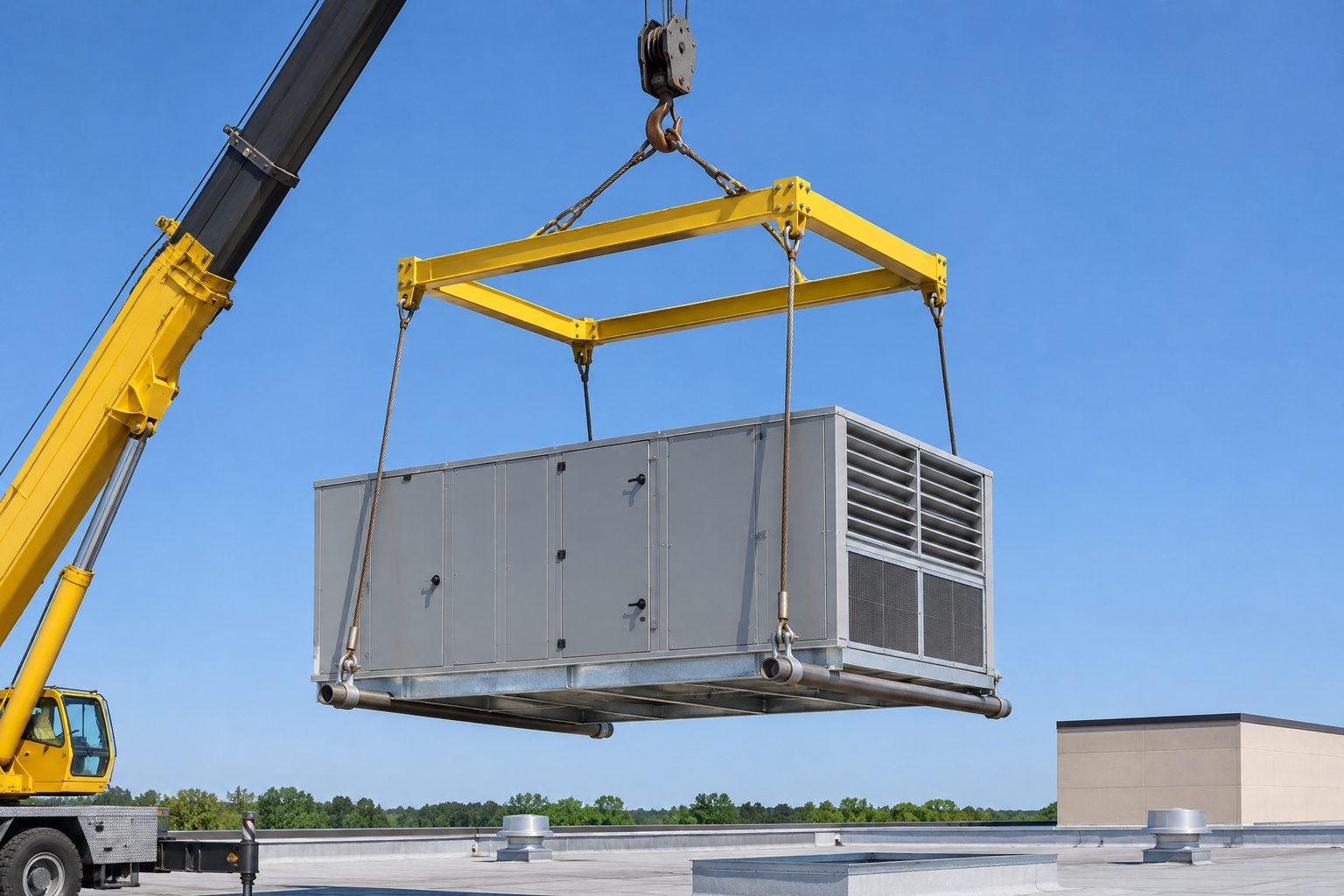
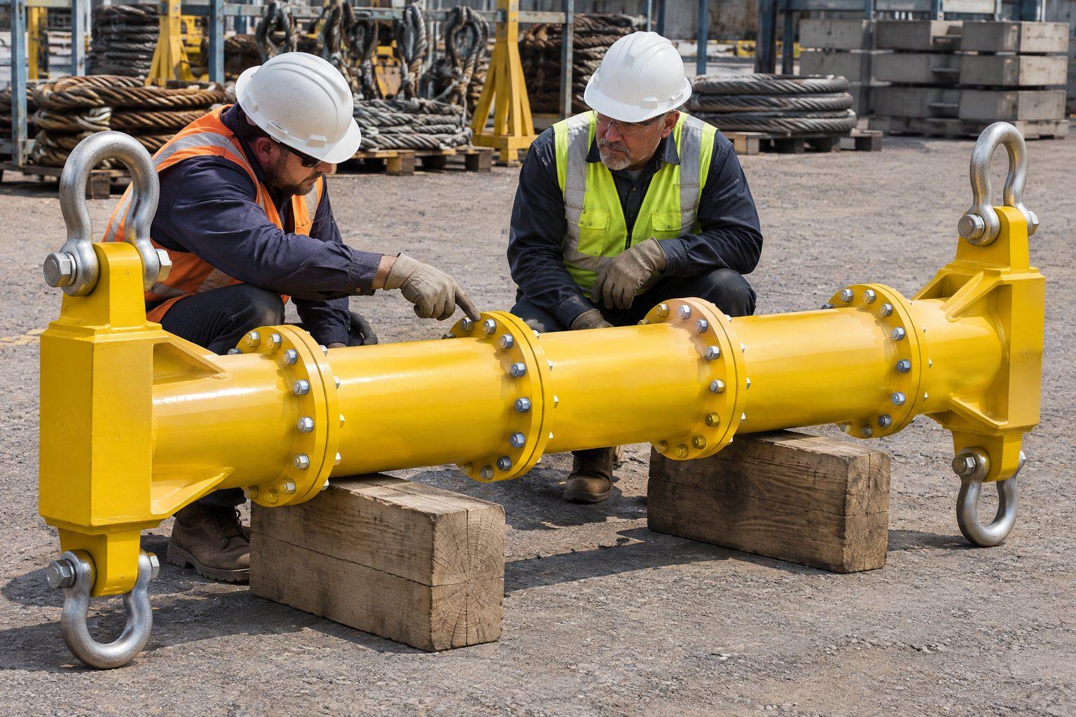
Spreader beams look simple, and that is the problem. A length of tube with a shackle at each end does not look like precision equipment, so it gets rigged the way the slings happen to fit. But a spreader is light precisely because it is designed for one load case — compression between two vertical drops — and every departure from that case moves force somewhere it was not designed to go. Most of the errors below are visible from the ground, in the photos a project proudly posts afterwards.
/01Bottom slings in line with the top slings.
The lifting points on the load are further apart than the beam, and the bottom slings run out at the same angle as the top slings, so each side of the rig is one straight line from hook to lug. At the beam end nothing changes direction, so no force goes into the beam. Take the beam away and the slings, the angles and the forces in the load would be exactly the same. The beam is a passenger.
The beam will not fail — but the load is now carrying all the compression the spreader was bought to remove, and whoever planned the lift believes it is not. A long panel, a tank or a module that cannot take end compression can buckle or crack. How big that squeeze is, angle by angle, is in sling angle compression force.
/02Bottom slings splayed wider still.
Now the bottom slings lean out further than the top slings lean in. At each beam end the bottom sling pulls outward harder than the top sling pulls inward, and the beam is what holds the two ends together — in tension. A modular beam is designed for compression: its flange bolts are sized for the shear and bending of a strut, not for pulling the joint apart. Tension the designer never allowed for adds to those stresses, and the beam can fail at a joint well below its rating. This rig is worse than the first: the load is still squeezed, and the beam is now at risk too.
The opposite fault — bottom slings leaning inward to lugs closer together than the beam ends — adds their inward pull to the top slings’, so the beam carries more compression than its chart allows for. The cure for all three is the same: make the beam span equal to the lifting point spacing, so the drops hang vertically. Makers’ instructions commonly allow the bottom slings no more than 6° from vertical.
/03Using a spreader as a lifting beam.
Hanging a load from the middle of a spreader, or from a strut, or rigging the whole beam from a single top sling, makes it a lifting beam — and puts it in bending. A spreader is a fraction of the section a lifting beam of the same capacity needs, so this is the error most likely to end with a bent beam and a dropped load. Load a spreader only at its two end links. If the job needs one top point or extra pick points along the length, use a lifting beam. The difference is in spreader beam vs lifting beam.
/04Top slings too short.
A spreader’s rating depends on its top sling angle as well as its span, and the chart gives the shortest top sling for each angle. Our 8 t modular beam at a 3 m span is rated 5 t at 45° to the vertical and needs top slings of at least 2.1 m to stay within it. Use 1.5 m slings because they were in the container and the angle opens past 45° — outside every row of the chart, with compression rising steeply. Measure the top slings, and read the column for the angle you actually rig.
/05An offset load on a beam rated by halves.
If the load’s centre of gravity is off centre, one end of the beam carries more than half. Modular beams are rated component by component — on the 8 t beam each end unit and link plate is rated 4 t — so a load within the beam’s chart can still overload one end. Work out each end’s share from the centre of gravity before the lift; centre of gravity in lifting shows how.
/06Mixed parts, wrong bolts, too many struts.
A modular beam is certified as a system, for the configurations in its chart. It stops being that system when:
- Components are mixed — struts from another size, another series or another maker. Flanges that bolt up are not the same as parts designed together.
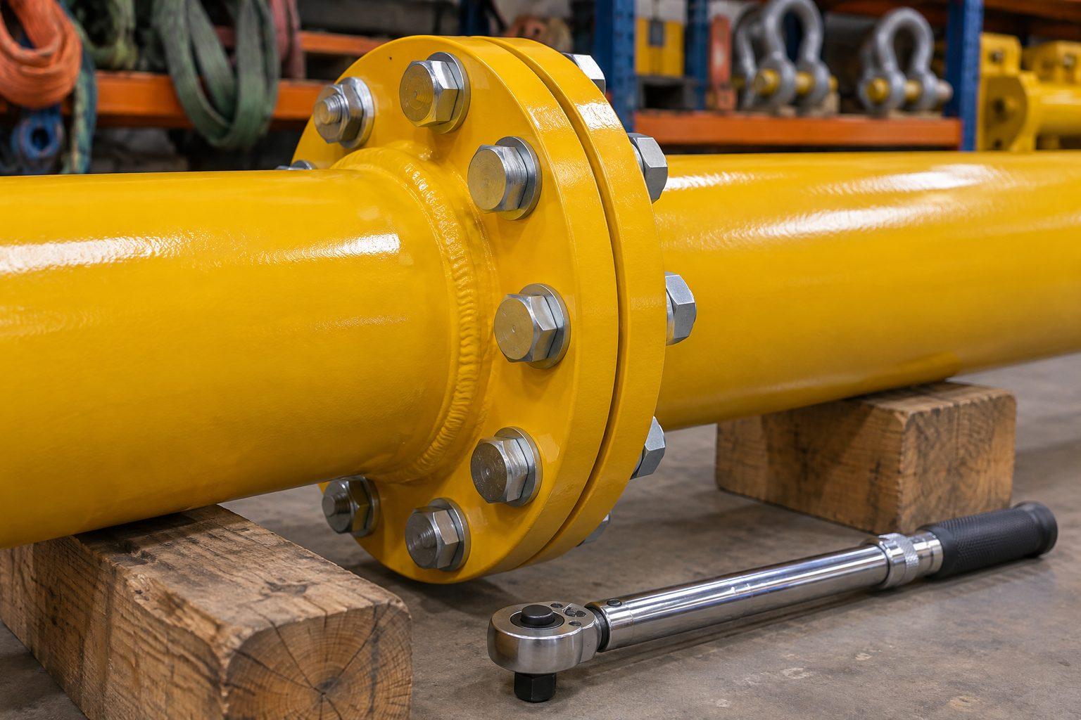
- Bolts are substituted or under-tightened. The 8 t beam specifies M10 × 30 grade 8.8 bolts, nuts and washers at 80 Nm; a hardware-store bolt of the right diameter is not a replacement.
- The span is not in the chart, or the beam carries more struts than allowed (six on the 8 t beam), or there is a flange joint at mid-span when the instructions put the longest strut in the middle.
- The beam is modified — a lug welded on, a hole drilled for a tag line. Any change voids the certificate until the maker re-rates it.
/07Clashes and twisted end links.
End links should hang toward the load, and no shackle or sling should bear on the beam itself. A sling bent over the end of the tube or a shackle jammed against a flange is carrying load in a direction nobody rated. Before the lift, take the slack out, stop, and look along the rig from both ends.
Before every spreader lift
Five checks from the ground.
IfDo the bottom slings hang vertically?
If not, change the span to match the lifting points. Makers commonly allow 6° at most.
IfIs the load hung only from the two end links?
Anything else is a lifting beam job.
IfAre the top slings at least the chart minimum for the span and angle?
If not, use the 45° column, or longer slings.
IfIs the centre of gravity central?
If not, check each end’s share against its own rating.
IfIs it one system, assembled to the instructions, with its marking and certificate?
No mixed parts, correct bolts and torque, span in the chart.
Common questions
- What angle can the bottom slings of a spreader beam be at?
- They should hang vertically. Makers’ instructions commonly allow no more than 6° from vertical. Beyond that the beam is either idle, in tension or overloaded in compression, depending on which way they lean.
- Can a spreader beam be used as a lifting beam?
- No, unless its instructions give a lifting-beam rating. A spreader is designed for compression and is much lighter than a lifting beam; a load hung from its middle puts it in bending.
- Why does a spreader beam not reduce the load on my lifting points?
- If the bottom slings are angled in line with the top slings, the beam carries nothing and the load and its lugs see the same forces as without it. The bottom slings must hang vertically.
- Can I mix struts from different spreader beams?
- No. A modular beam is certified as one system for the configurations in its chart. Parts from another size, series or maker are not covered by that certificate.
- What happens if the top slings are too short?
- The top sling angle opens beyond the chart row you chose, the compression in the beam rises and the beam is overloaded. Use the chart’s minimum top sling length for the span and angle.
Spreader beams with full span charts
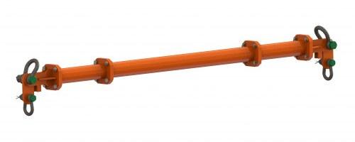 IH-LR-BH-MSB-4Modular Spreader Beam — 4 t, 0.5–4.5 m Span, up to 4 t WLL, EN 13155
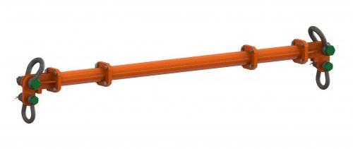 IH-LR-BH-MSB-8Modular Spreader Beam — 8 t, 0.5–4.5 m Span, up to 8 t WLL, EN 13155
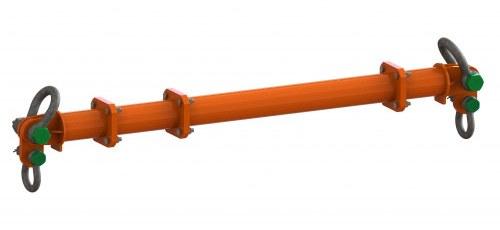 IH-LR-BH-MSB-13Modular Spreader Beam — 13 t, 0.5–6.5 m Span, up to 13 t WLL, EN 13155
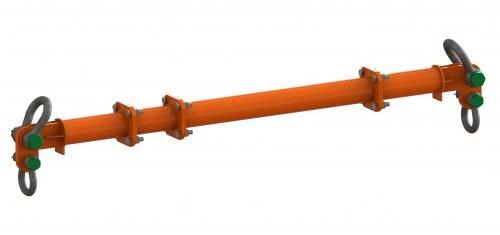 IH-LR-BH-MSB-24Modular Spreader Beam — 24 t, 1–8 m Span, up to 24 t WLL, EN 13155
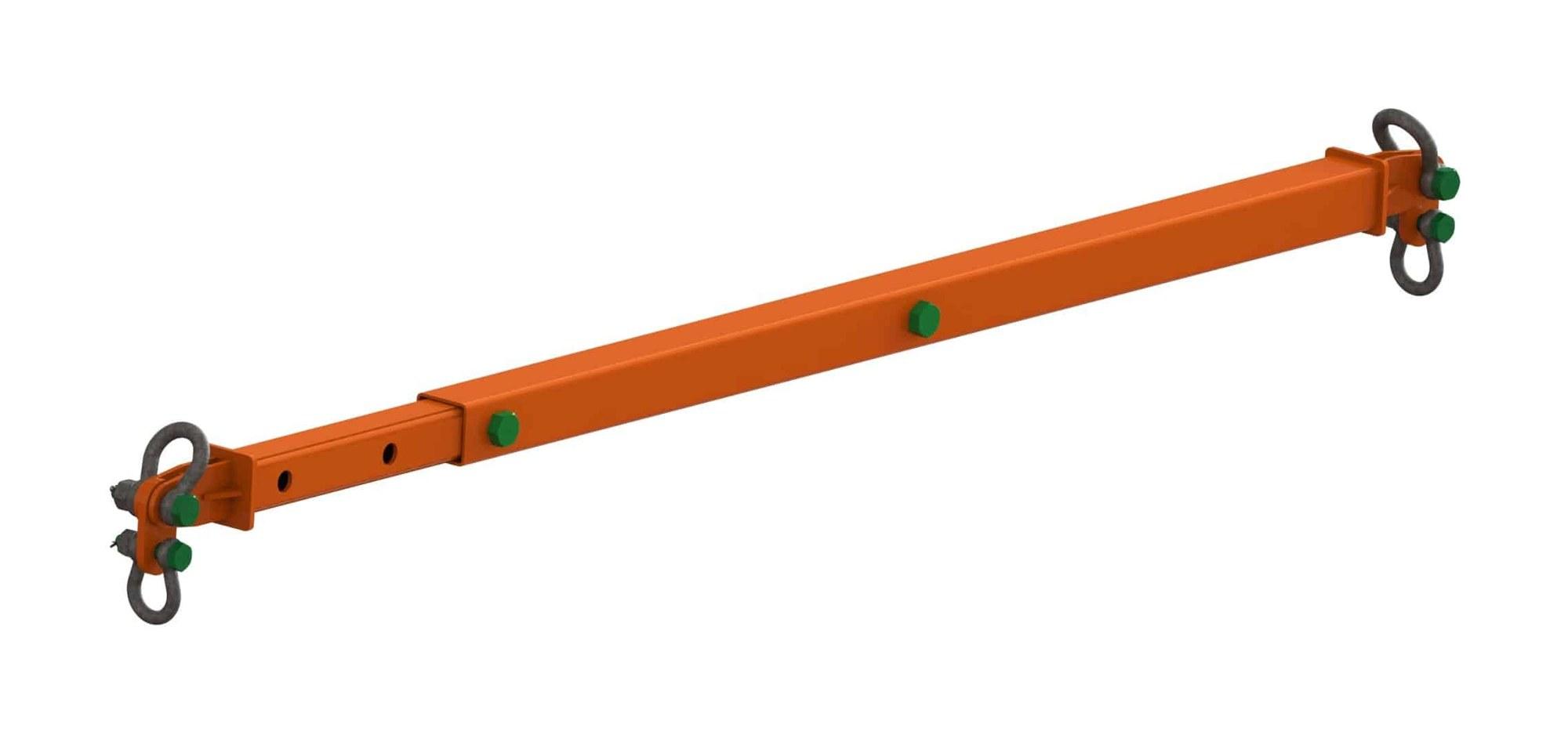 IH-LR-BH-TSBTelescopic Spreader Beams — 4 t to 16 t, EN 13155
 IH-LR-BH-FSBFixed & Custom Spreader Beams — EN 13155