Most riggers know the rule: open the sling angle and the load in each leg goes up. Fewer can say why, and fewer still think about where the extra force goes. It does not disappear — it pushes the lifting points toward each other, and the load between them has to resist it. For a solid steel block that hardly matters. For a thin-walled tank, a long precast panel, a timber truss or a cladding unit, it can be the force that damages the load before it ever leaves the ground.
/01One leg at a time.
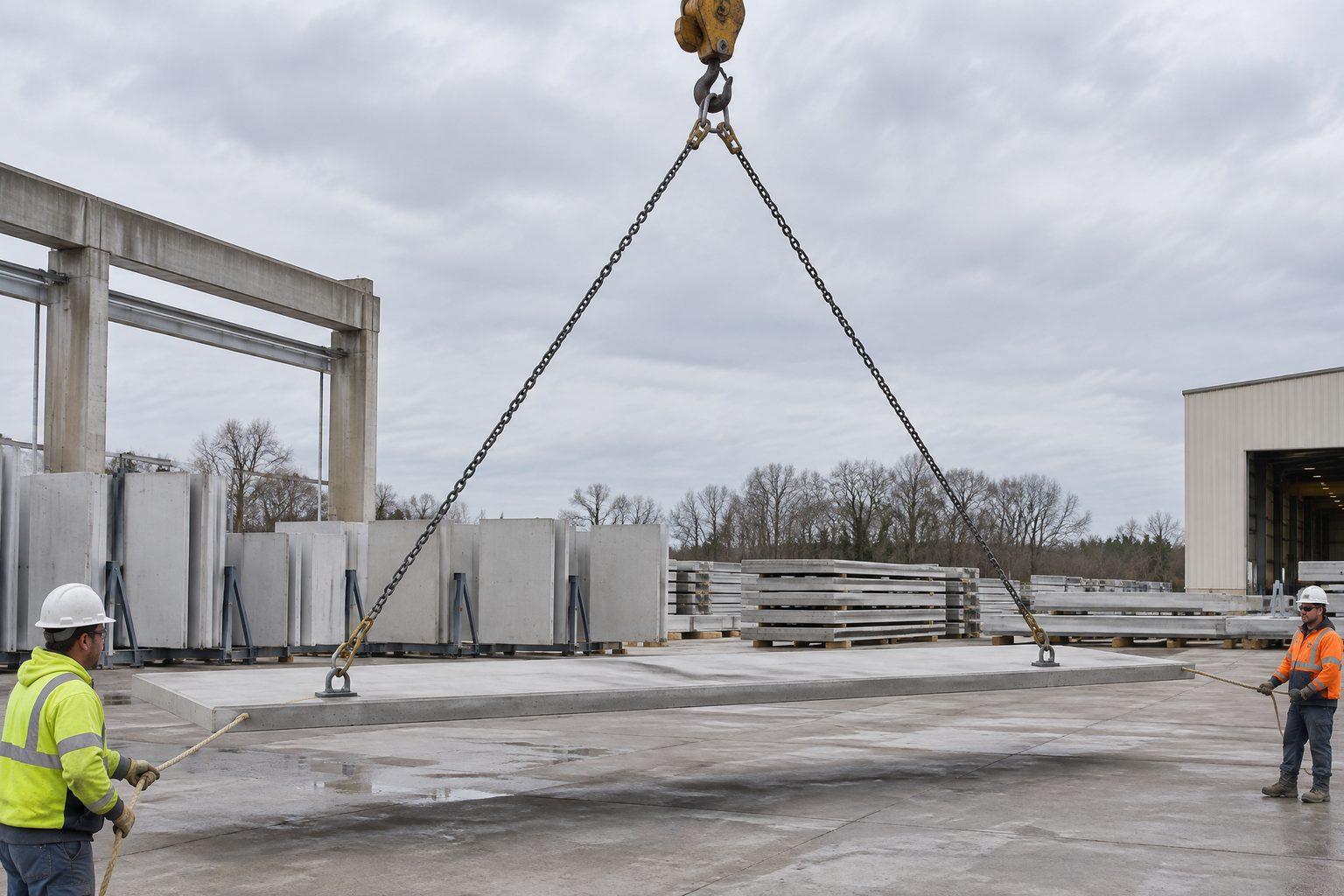
Take a 12 t load with its centre of gravity in the middle, lifted by a two-leg sling from lugs at each end. Each lug carries half the weight: 6 t. If the legs hung straight down, each would carry exactly 6 t. But the legs meet at a hook above the middle of the load, so each one leans inward — say at 40° from vertical.
A sling can only pull along its own length. Pulling at 40°, part of that pull is upward and part is sideways, toward the other lug. The upward part has to equal the 6 t share or the load does not leave the ground; the sideways part comes along whether you want it or not. Because the sling has to supply both, its tension is larger than either.
/02The triangle does the maths.
The three forces at the lug — vertical, horizontal and the pull in the sling — form a right-angled triangle with the same 40° angle as the sling. You can solve it by drawing it to scale on squared paper, or with two lines of trigonometry:
- Sling tension = 6 t ÷ cos 40° = 6 ÷ 0.766 = 7.8 t.
- Sideways pull = 6 t × tan 40° = 6 × 0.839 = 5.0 t.
So the answer to “will a 6.5 t shackle and sling do on each leg?” is no, even though two of them add up to 13 t on a 12 t load. Each leg sees 7.8 t; the next size up, an 8.5 t shackle, is the one that works. The same factors, for every angle, are tabulated in the sling angle chart.
| Angle from vertical | Tension in each leg | Compression in the load |
|---|---|---|
| 0° (legs vertical) | 5.0 t | 0 |
| 15° | 5.2 t | 1.3 t |
| 20° | 5.3 t | 1.8 t |
| 30° | 5.8 t | 2.9 t |
| 40° | 6.5 t | 4.2 t |
| 45° | 7.1 t | 5.0 t |
| 60° | 10.0 t | 8.7 t |
Notice how differently the two columns grow. Between 0° and 30° the leg tension rises only 16%, but the compression goes from nothing to almost 30% of the load. By 60° the load is being squeezed with nearly its own weight. Angles here are measured from vertical; many US charts measure from horizontal, so their 60° is this table’s 30°.
/03The mistake that doubles it.
Two lugs, two inward pulls of 5.0 t each — so the load is squeezed with 10 t? No. The two pulls are the same force seen from each end, the way the rope in a tug of war carries the pull of one team, not both added together. One end pushes inward with 5.0 t; the other end resists with 5.0 t; the load between them is in 5.0 t of compression. Doubling it over-designs the load check, which is harmless; the reverse mistake — forgetting the compression altogether — is the one that crushes things.
/04What the compression does.
- It squeezes the load. Long, slender or hollow loads — pipe spools, tanks, ducting, precast panels, modules and trusses — can bow, buckle or crack. Ask the designer of the load what end compression it can take.
- It loads the lifting points sideways. A lug or eye bolt loaded at an angle carries much less than its vertical rating; see eye bolts and angled loads and how to rig a shackle correctly.
- It acts on the casing, not just the lugs. A sling that touches the side of a unit on its way up presses into it with this force — the usual way a crane lift dents the cladding of plant and equipment.
/05Where a spreader beam comes in.
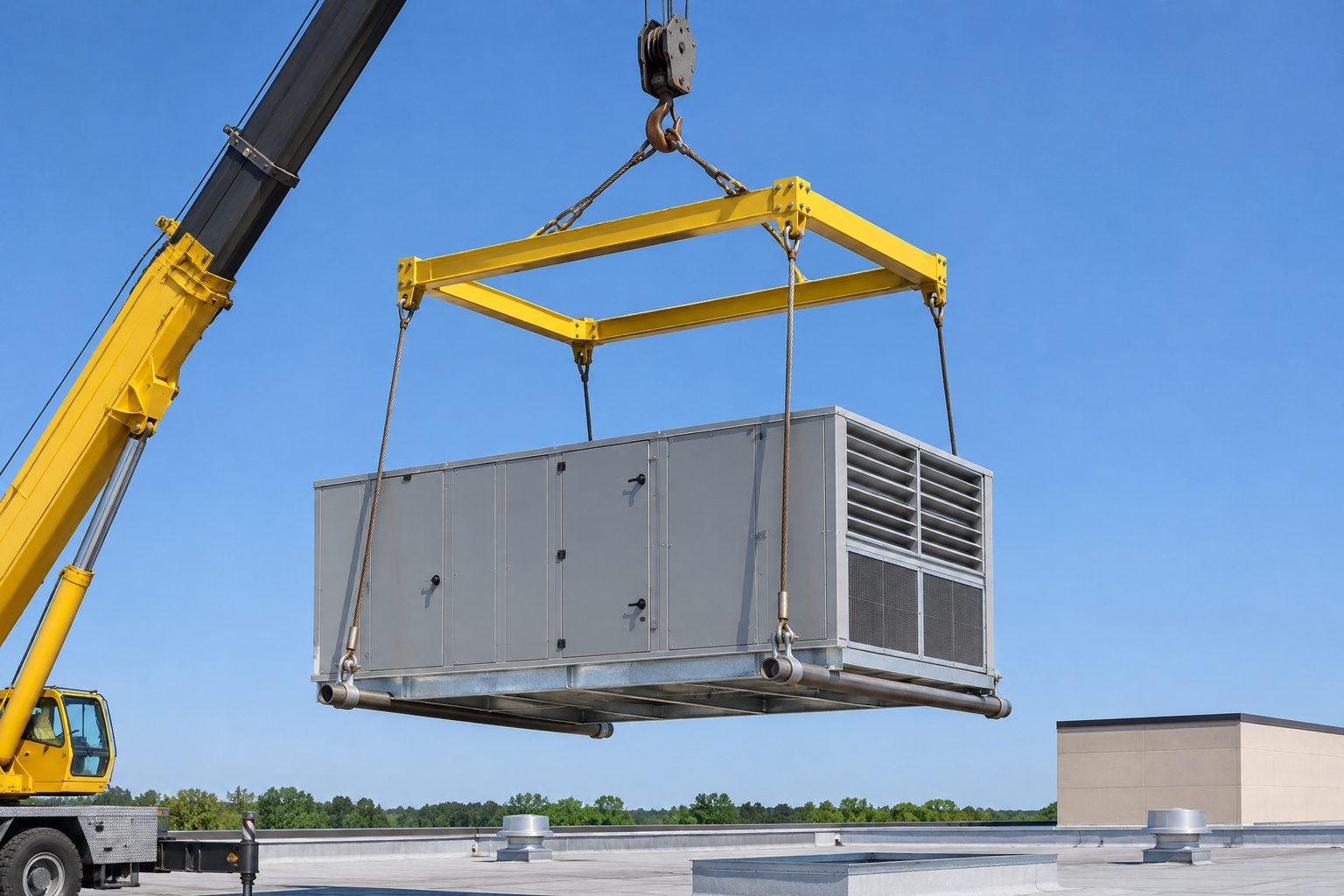
A spreader beam moves the angle above the load. The bottom slings hang vertically from the beam ends to the lugs, so the load feels no sideways pull at all. The top slings still lean in toward the hook, and their sideways pull is still share × tan(angle) — but now the beam takes it, as compression, instead of the load. More on the difference in spreader beam vs lifting beam.
You can see the compression in a spreader beam’s load chart. Our 8 t modular spreader beam built to a 4 m span is rated:
| Top slings to vertical | Rated load | Compression in the beam |
|---|---|---|
| 45° | 3 t | 1.5 t |
| 30° | 5 t | 1.4 t |
| 20° | 8 t | 1.5 t |
Three very different ratings, but the compression they put into the beam is about the same: roughly 1.5 t, which is what a 4 m strut of that section will carry. Steeper top slings mean less squeeze per tonne of load, so the same beam lifts more. The price is length — the chart’s minimum top sling at 4 m goes from 2.8 m at 45° to 5.8 m at 20° — so the angle you can use is often set by the headroom.
Common questions
- Why is the force in an angled sling greater than the load it carries?
- A sling pulls along its own length. At an angle, only part of that pull is upward; the rest is sideways. The sling must supply the full upward share plus the sideways part, so its tension is share ÷ cos(angle from vertical).
- How do I work out the compression in the load?
- For a symmetric two-leg lift, compression = half the load × tan(angle from vertical). At 45° that is half the load; at 30°, about 29% of the load.
- Is the compression doubled because both legs pull inward?
- No. The two inward pulls balance each other; the load is in compression equal to one of them.
- How can I reduce the compression?
- Use longer slings so the legs hang steeper, or use a spreader beam so the bottom slings hang vertically and the beam takes the compression instead of the load.
- Do four-leg slings squeeze the load too?
- Yes, in both directions — along the length and across the width — whenever the legs meet at one hook. A spreader frame keeps all four legs vertical.
For lifts that must not be squeezed
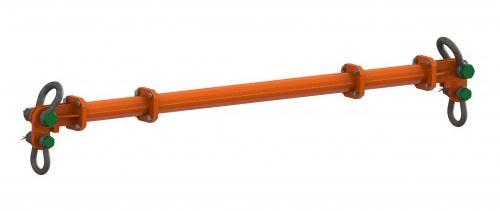 IH-LR-BH-MSB-8Modular Spreader Beam — 8 t, 0.5–4.5 m Span, up to 8 t WLL, EN 13155
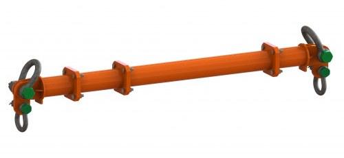 IH-LR-BH-MSB-13Modular Spreader Beam — 13 t, 0.5–6.5 m Span, up to 13 t WLL, EN 13155
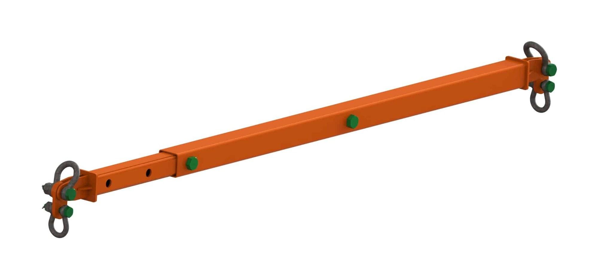 IH-LR-BH-TSBTelescopic Spreader Beams — 4 t to 16 t, EN 13155
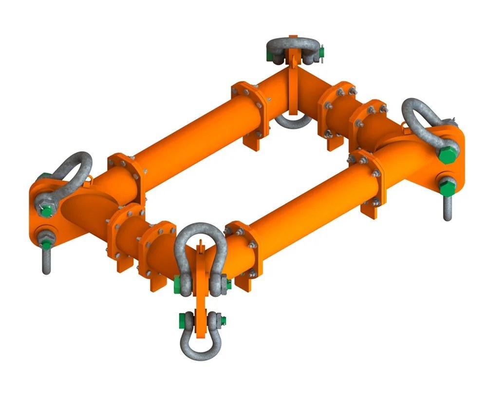 IH-LR-BH-MSFModular Spreader Frames — 10 t to 90 t, EN 13155
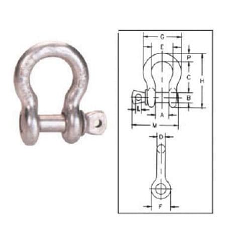 IH-LR-SH-G209Screw Pin Anchor Shackle — G-209 Pattern, 0.333–55 t WLL