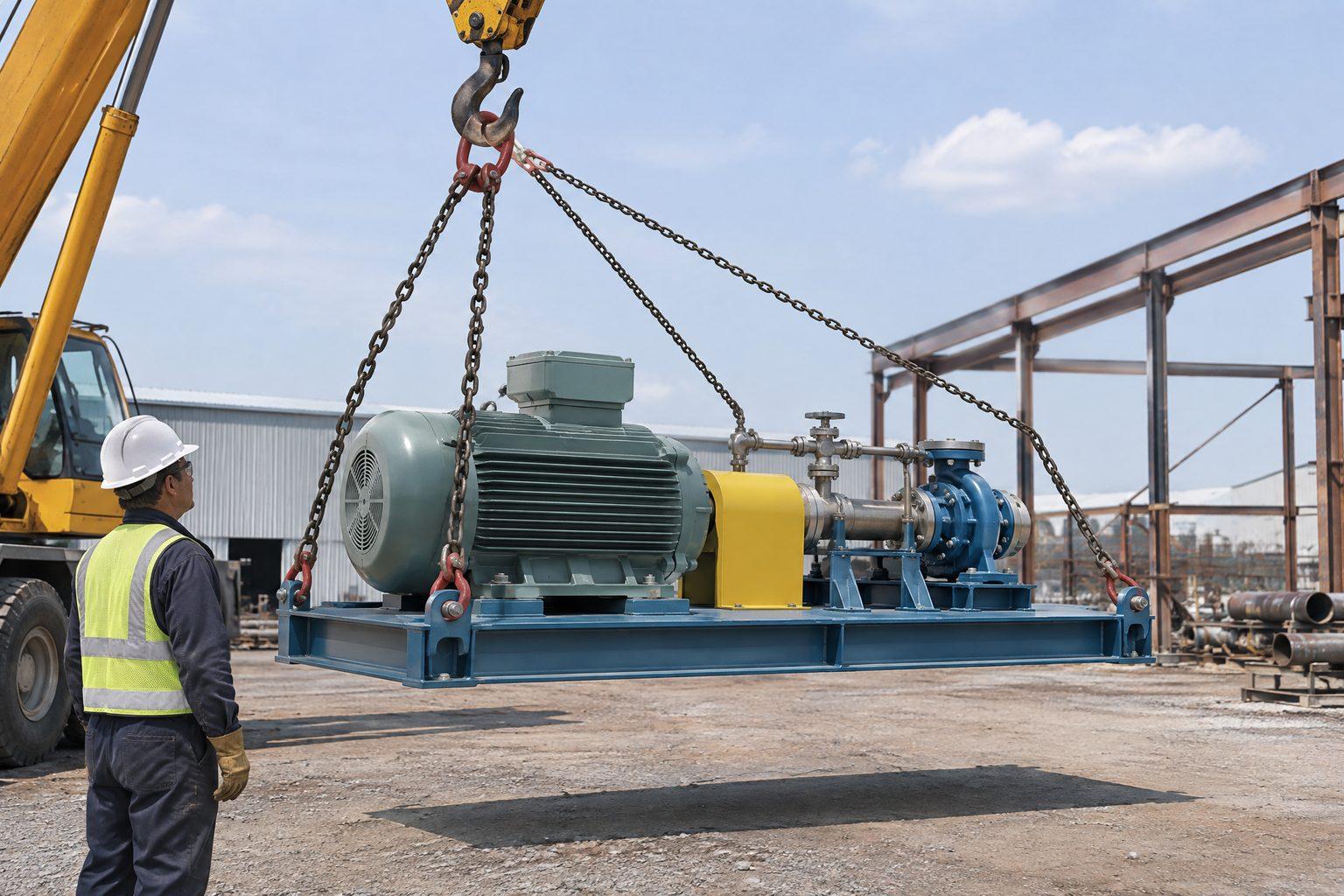
Every lift plan asks for the weight. The better ones also ask where the weight is. A skid with its pump at one end, a valve with its actuator, a tank with liquid left in it, a generator set with the fuel tank full — all of them weigh the same whichever way round you lift them, but they hang very differently. The centre of gravity decides how much each leg carries, whether the load comes up level, and in the worst case whether it stays the right way up.
/01What the centre of gravity is.
Engineers treat the whole weight of an object as if it acted at one point: the centre of gravity. For a solid block of one material it is in the middle. Change the shape — a step, a bracket, a motor on one end — and it moves toward the bulk. Change the contents and it moves again: an empty box tips off a shelf when half of it overhangs the edge, but fill one end with something heavy and it tips much sooner. So the CoG is a property of the load as it will be lifted, including anything left inside it.
Where to get it:
- The maker’s data — the general arrangement drawing or rigging sheet for skids, packaged plant, vessels and modules usually marks the CoG with the quartered-circle symbol.
- Calculation — from the weights and positions of the main parts, for fabrications made in-house.
- Weighing — load cells under each support give each corner’s share, from which the CoG follows directly.
- A trial lift — raise the load a few centimetres, stop and watch which way it tilts before committing to the full lift.
Allow for what the drawing may not show: water left after a hydrotest, fuel, packing, loose items and accessories fitted on site.
/02The rule: CoG under the hook.
A suspended load is free to swing and turn, and it settles where its weight acts straight down through the hook. That is all the planning needs: put the hook over the CoG and the load comes up level; put it anywhere else and the load turns until the CoG gets there on its own.
/03How the legs share the load.
With the hook over the CoG, each lifting point carries a share in inverse proportion to its distance from the CoG — the lever rule. For a 10 t load on lugs 4 m apart, with the CoG 1 m from lug A and 3 m from lug B:
- Lug A carries 10 × 3 ÷ 4 = 7.5 t; lug B carries 10 × 1 ÷ 4 = 2.5 t.
- With the hook 2.2 m above the lugs, leg A leans 1 m off vertical and leg B 3 m. Leg A’s tension is 7.5 × 2.42 ÷ 2.2 = 8.2 t; leg B’s is 2.5 × 3.72 ÷ 2.2 = 4.2 t.
- The legs are different lengths — 2.4 m and 3.7 m — because the hook is not over the middle of the load.
Two consequences. A two-leg sling’s rating assumes the legs share equally: one marked 10 t for angles up to 45° has legs of about 7.1 t each (10 ÷ 1.4), so leg A at 8.2 t is overloaded although the load matches the marking — and leg B, at 54° from vertical, is outside that band altogether. And equal-length legs cannot put the hook over this CoG: the load would tilt toward lug A until it found its own balance. Use legs of the right lengths, or adjust one with a shortening clutch.
/04How far an off-centre load tilts.
Hang a load from a single point and it tilts until the CoG is under that point. The angle is set by two distances measured on the load: how far the CoG is off to the side of the lifting point (e) and how far below it (h). The tilt is tan⁻¹(e ÷ h). With the CoG 0.3 m to one side and 0.5 m below the lifting point the load tilts about 31°; raise the CoG to 0.2 m below the lifting point and the same offset tilts it about 56°. A high CoG magnifies every error in where the lifting point is placed.
/05Above or below: stability.
Lift a load at two points and it can rotate freely about the line joining them — the slings do not change length as it turns. Whether it stays upright depends on where the CoG sits relative to that line.
- CoG below the line — lugs on top of the load. If the load is disturbed it swings back, like a pendulum. This is the stable case and the reason lifting points are best placed above the CoG.
- CoG above the line — lifting from the base, or a single bar through the bottom of the load. The load is balanced like a pencil on its point: any disturbance, a gust or a snag, and it rolls over about the lifting points.
Four lifting points that are not in one line remove that freedom — the load cannot roll about a single axis — but only if all four legs stay loaded. Base-lifted loads are where engineered lifting bars and frames earn their keep; see lifting bars for air handling units.
/06Offset loads under a spreader beam.
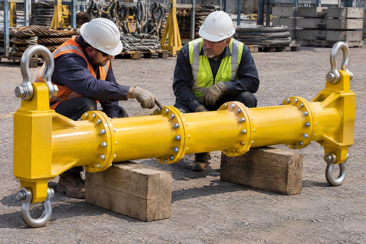
A spreader beam does not change the rule: the hook still has to be over the CoG, so with an offset load the top slings are unequal lengths and one end of the beam carries more than half. Modular beams are rated component by component. On our 8 t modular spreader beam each end unit and link plate is rated 4 t. Built to 3 m and rigged at 30°, the chart allows 8 t — but put a 7 t load on it with its CoG 0.4 m off centre and the near end carries 7 × 1.9 ÷ 3 = 4.4 t. The beam is within its chart; the end unit is not.
For loads that are always offset, a lifting beam with an offset or sliding top lug puts the hook over the CoG and keeps the load level. Loads that must be hung away from the crane altogether — into a building, under an overhang — use a counterweight lifting beam, whose design depends entirely on knowing the CoG.
Common questions
- What is the centre of gravity of a load?
- The single point through which the whole weight of the load acts. It depends on the load’s shape and on what it is made of and contains.
- Why does a load tilt when it is lifted?
- A suspended load turns until its centre of gravity is directly under the hook. If the hook is not over the centre of gravity at the start, the load tilts until it is.
- How do I calculate the load on each sling leg with an offset centre of gravity?
- With the hook over the centre of gravity, each lifting point carries the load times the distance from the other point to the centre of gravity, divided by the distance between points. Then divide by the cosine of that leg’s angle from vertical for its tension.
- Why are lifting points on top of a load safer?
- A load lifted at two points can rotate about the line between them. With the points above the centre of gravity it hangs stably; with them below, it can topple.
- How do I find the centre of gravity of a skid or module?
- From the maker’s general arrangement drawing, by calculation from component weights, by weighing each support with load cells, or with a short trial lift to see which way it tilts.
- Can a spreader beam lift a load with an offset centre of gravity?
- Yes, with the hook over the centre of gravity and unequal top slings, provided each end of the beam stays within its own rating as well as the beam’s chart.
Beams for balanced and offset loads
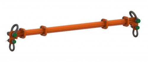 IH-LR-BH-MSB-8Modular Spreader Beam — 8 t, 0.5–4.5 m Span, up to 8 t WLL, EN 13155
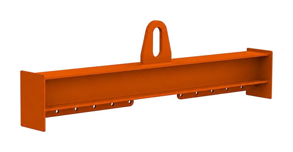 IH-LR-BH-FLBFixed Lifting Beams — EN 13155
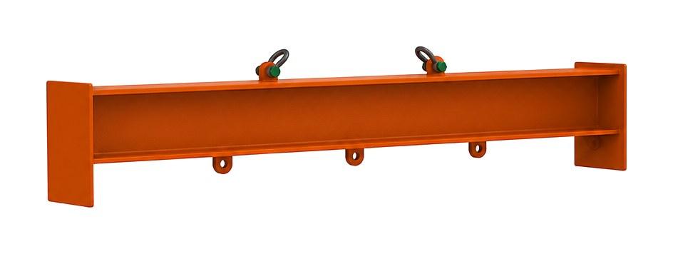 IH-LR-BH-SSBSemi-Spreader Lifting Beams — EN 13155
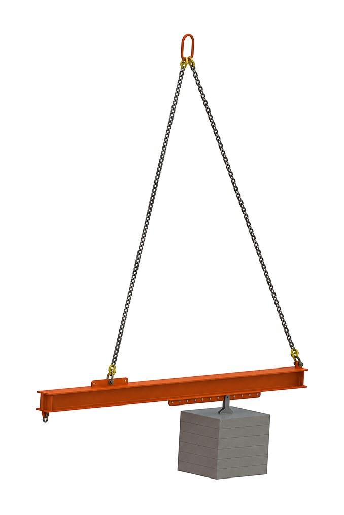 IH-LR-BH-CWBCounterweight Lifting Beams — EN 13155
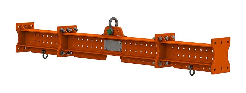 IH-LR-BH-MCB-16Multi-Configuration Modular Lifting Beam — 16 t Beam, 23 t Semi-Spreader