
Modular Spreader Beam — 24 t, 1–8 m Span, up to 24 t WLL, EN 13155
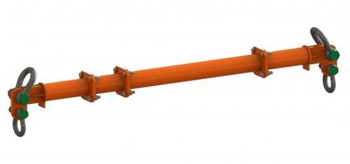
Modular spreader beam rated to 24 t, built from two end units and bolt-in struts to any span from 1 m to 8 m. The size table is the load chart: rated load and minimum top sling length at 45°, 30° and 20° sling angles for every span.
Key features
- Product type: Modular spreader beam
- Pattern / standard: EN 13155
- Size range: Span 1–8 m
- Working load limit: Up to 24 t (by span and sling angle)
- Product type
- Modular spreader beam
- Material
- Steel, bolted modular construction
Product description
A bolt-together spreader beam rated up to 24 t, made of two end units and interchangeable struts. It can be built to any span from 1 m to 8 m in the steps of its chart, and taken apart again for transport and storage. The beam takes its load at the two end links only and works in compression, so it is light for its capacity and suits long loads lifted at two points.
Span chart
Each row is one span: the rated load at a top sling angle of 45°, 30° and 20° to the vertical, and the shortest top sling leg that keeps the angle within that limit. At 45° the full 24 t is available to a span of 4 m; beyond that the chart steps the load down.
The beam is certified for every configuration in its chart, so changing the span does not need a new test or certificate. Pre-use checks and periodic thorough examination still apply.
Components and bolts
Each end unit and link plate is rated 12 t, half the beam's 24 t, because the beam is modular and every component is rated on its own. With an off-centre load, check that neither end carries more than 12 t. Struts join with M20 × 50 grade 8.8 bolts, nuts and washers tightened to 160 Nm; a full set plus spares is supplied. No more than seven components in one beam, end units included.
Rules for use
- Load the beam only at its two end links. Never hang a load from a strut.
- Keep the top sling angle at 45° to the vertical or less, and read the chart for the angle you rig.
- End links hang downward, toward the load; bottom slings run vertically to the load.
- Check that no shackle or sling clashes with the beam.
- Put the longest strut in the middle, so there is no flange joint at the centre of the beam.
Ordering
Quote the part number of the span you need from the table, or send the load weight, the distance between its lifting points and the hook height, and we will choose the size and span. Top and bottom rigging (shackles, slings and master links) can be quoted with the beam. Custom struts, special end links and tag-line points are available to order.
Identification
| Parameter | Value |
|---|---|
| Product type | Modular spreader beam |
| Pattern / standard | EN 13155 |
| Sizes | 15 |
Performance
| Parameter | Value |
|---|---|
| Working load limit | Up to 24 t (by span and sling angle) |
| Sling angle | 45° to vertical, maximum |
| End unit WLL | 12 t each end (24 t combined) |
Dimensions
| Parameter | Value |
|---|---|
| Size range | Span 1–8 m |
Construction
| Parameter | Value |
|---|---|
| Material | Steel, bolted modular construction |
| Strut bolts | M20 × 50 grade 8.8, 160 Nm |
Compliance
| Parameter | Value |
|---|---|
| Certification | Declaration of conformity; user instructions with load chart |
Shipping & lead time
Sizes & part numbers
15 sizes- Indus part no.IH-LR-BH-MSB-24-0100
- Span
- 1 m
- WLL, 45° to vertical (t)
- 24
- WLL, 30° to vertical (t)
- 24
- WLL, 20° to vertical (t)
- 24
- Min. top sling, 45° to vertical (m)
- 0.6
- Min. top sling, 30° to vertical (m)
- 0.9
- Min. top sling, 20° to vertical (m)
- 1.3
- Indus part no.IH-LR-BH-MSB-24-0150
- Span
- 1.5 m
- WLL, 45° to vertical (t)
- 24
- WLL, 30° to vertical (t)
- 24
- WLL, 20° to vertical (t)
- 24
- Min. top sling, 45° to vertical (m)
- 0.9
- Min. top sling, 30° to vertical (m)
- 1.4
- Min. top sling, 20° to vertical (m)
- 2.1
- Indus part no.IH-LR-BH-MSB-24-0200
- Span
- 2 m
- WLL, 45° to vertical (t)
- 24
- WLL, 30° to vertical (t)
- 24
- WLL, 20° to vertical (t)
- 24
- Min. top sling, 45° to vertical (m)
- 1.3
- Min. top sling, 30° to vertical (m)
- 1.9
- Min. top sling, 20° to vertical (m)
- 2.8
- Indus part no.IH-LR-BH-MSB-24-0250
- Span
- 2.5 m
- WLL, 45° to vertical (t)
- 24
- WLL, 30° to vertical (t)
- 24
- WLL, 20° to vertical (t)
- 24
- Min. top sling, 45° to vertical (m)
- 1.7
- Min. top sling, 30° to vertical (m)
- 2.4
- Min. top sling, 20° to vertical (m)
- 3.5
- Indus part no.IH-LR-BH-MSB-24-0300
- Span
- 3 m
- WLL, 45° to vertical (t)
- 24
- WLL, 30° to vertical (t)
- 24
- WLL, 20° to vertical (t)
- 24
- Min. top sling, 45° to vertical (m)
- 2
- Min. top sling, 30° to vertical (m)
- 2.9
- Min. top sling, 20° to vertical (m)
- 4.3
- Indus part no.IH-LR-BH-MSB-24-0350
- Span
- 3.5 m
- WLL, 45° to vertical (t)
- 24
- WLL, 30° to vertical (t)
- 24
- WLL, 20° to vertical (t)
- 24
- Min. top sling, 45° to vertical (m)
- 2.4
- Min. top sling, 30° to vertical (m)
- 3.4
- Min. top sling, 20° to vertical (m)
- 5
- Indus part no.IH-LR-BH-MSB-24-0400
- Span
- 4 m
- WLL, 45° to vertical (t)
- 24
- WLL, 30° to vertical (t)
- 24
- WLL, 20° to vertical (t)
- 24
- Min. top sling, 45° to vertical (m)
- 2.7
- Min. top sling, 30° to vertical (m)
- 3.9
- Min. top sling, 20° to vertical (m)
- 5.7
- Indus part no.IH-LR-BH-MSB-24-0450
- Span
- 4.5 m
- WLL, 45° to vertical (t)
- 20
- WLL, 30° to vertical (t)
- 24
- WLL, 20° to vertical (t)
- 24
- Min. top sling, 45° to vertical (m)
- 3.1
- Min. top sling, 30° to vertical (m)
- 4.4
- Min. top sling, 20° to vertical (m)
- 6.5
Show all 15 sizesShow fewer sizes
- Indus part no.IH-LR-BH-MSB-24-0500
- Span
- 5 m
- WLL, 45° to vertical (t)
- 17
- WLL, 30° to vertical (t)
- 24
- WLL, 20° to vertical (t)
- 24
- Min. top sling, 45° to vertical (m)
- 3.4
- Min. top sling, 30° to vertical (m)
- 4.9
- Min. top sling, 20° to vertical (m)
- 7.2
- Indus part no.IH-LR-BH-MSB-24-0550
- Span
- 5.5 m
- WLL, 45° to vertical (t)
- 14
- WLL, 30° to vertical (t)
- 24
- WLL, 20° to vertical (t)
- 24
- Min. top sling, 45° to vertical (m)
- 3.8
- Min. top sling, 30° to vertical (m)
- 5.4
- Min. top sling, 20° to vertical (m)
- 7.9
- Indus part no.IH-LR-BH-MSB-24-0600
- Span
- 6 m
- WLL, 45° to vertical (t)
- 11
- WLL, 30° to vertical (t)
- 20
- WLL, 20° to vertical (t)
- 24
- Min. top sling, 45° to vertical (m)
- 4.1
- Min. top sling, 30° to vertical (m)
- 5.9
- Min. top sling, 20° to vertical (m)
- 8.7
- Indus part no.IH-LR-BH-MSB-24-0650
- Span
- 6.5 m
- WLL, 45° to vertical (t)
- 10
- WLL, 30° to vertical (t)
- 17
- WLL, 20° to vertical (t)
- 24
- Min. top sling, 45° to vertical (m)
- 4.5
- Min. top sling, 30° to vertical (m)
- 6.4
- Min. top sling, 20° to vertical (m)
- 9.4
- Indus part no.IH-LR-BH-MSB-24-0700
- Span
- 7 m
- WLL, 45° to vertical (t)
- 8
- WLL, 30° to vertical (t)
- 14
- WLL, 20° to vertical (t)
- 23
- Min. top sling, 45° to vertical (m)
- 4.8
- Min. top sling, 30° to vertical (m)
- 6.9
- Min. top sling, 20° to vertical (m)
- 10.1
- Indus part no.IH-LR-BH-MSB-24-0750
- Span
- 7.5 m
- WLL, 45° to vertical (t)
- 7
- WLL, 30° to vertical (t)
- 12
- WLL, 20° to vertical (t)
- 20
- Min. top sling, 45° to vertical (m)
- 5.2
- Min. top sling, 30° to vertical (m)
- 7.4
- Min. top sling, 20° to vertical (m)
- 10.8
- Indus part no.IH-LR-BH-MSB-24-0800
- Span
- 8 m
- WLL, 45° to vertical (t)
- 6
- WLL, 30° to vertical (t)
- 11
- WLL, 20° to vertical (t)
- 17
- Min. top sling, 45° to vertical (m)
- 5.5
- Min. top sling, 30° to vertical (m)
- 7.9
- Min. top sling, 20° to vertical (m)
- 11.6
Span — Distance between the lifting points the load hangs from, as the load chart prints it. WLL, 45° to vertical — Working load limit — the most the part may carry in service, as the manufacturer rates it. WLL, 30° to vertical — Working load limit — the most the part may carry in service, as the manufacturer rates it. WLL, 20° to vertical — Working load limit — the most the part may carry in service, as the manufacturer rates it. Min. top sling, 45° to vertical — Shortest top sling leg that keeps the sling angle within the stated limit at this span, as the load chart gives it. Min. top sling, 30° to vertical — Shortest top sling leg that keeps the sling angle within the stated limit at this span, as the load chart gives it. Min. top sling, 20° to vertical — Shortest top sling leg that keeps the sling angle within the stated limit at this span, as the load chart gives it. Ask us for the dimension drawing if you need it stamped.
WLL is the most the part may carry in service. Proof and breaking loads are test figures — never lift to them. Each load is shown in the unit the manufacturer rates the part in, and a size ships with the manufacturer’s test certificate.
What is the Modular Spreader Beam — 24 t, 1–8 m Span used for?▾
How do I read part numbers such as IH-LR-BH-MSB-24-0100 for the Modular Spreader Beam — 24 t, 1–8 m Span?▾
What spans can the Modular Spreader Beam — 24 t, 1–8 m Span be built to?▾
How do I read the span chart for the Modular Spreader Beam — 24 t, 1–8 m Span?▾
Why does the Modular Spreader Beam — 24 t, 1–8 m Span carry less at wide sling angles?▾
What are the Modular Spreader Beam — 24 t, 1–8 m Span struts and bolts made of and tightened to?▾
Which standard and documents come with the Modular Spreader Beam — 24 t, 1–8 m Span?▾
What rigging goes with the Modular Spreader Beam — 24 t, 1–8 m Span?▾
What are the rules for using the Modular Spreader Beam — 24 t, 1–8 m Span?▾
How does the Modular Spreader Beam — 24 t, 1–8 m Span compare with the Modular Spreader Beam — 34 t, 1–10 m Span?▾
Can you ship the Modular Spreader Beam — 24 t, 1–8 m Span outside the UAE?▾
What is the lead time on the Modular Spreader Beam — 24 t, 1–8 m Span?▾
Shipped worldwide from our Dubai warehouse. Transit, routes and documentation for 136 destinations
From the blog
Written about this part
Lifting & rigging
Spreader beam vs lifting beam: how each carries the load, and how to choose
A lifting beam hangs from one top point and carries the load in bending. A spreader beam hangs from two top slings and only holds them apart, in compression. That one difference decides the weight of the beam, the headroom it needs and the loads it suits.
7 min read
Lifting & rigging
Bolted flange vs end cap spreader beams: two modular systems, and why rules decide between them
Modular spreader beams come in two families. Bolted-flange systems join end units and fixed-length struts with flange bolts; end-cap systems pin two end fittings into a length of pipe. How each is built, what each does well, and why the question of who supplies the pipe matters more than the engineering.
6 min read
Lifting & rigging
Spreader beam misuse: seven rigging errors that turn a spreader into a hazard
A spreader beam is designed for one load case: vertical drops at its ends, angled top slings, compression in between. Change the rigging and the forces change with it — the beam can end up doing nothing, being pulled apart, bent, or overloaded at one end. Seven common errors, why each matters, and how to spot them before the lift.
6 min read
Engineers viewing this also looked at
Modular Spreader Beam — 34 t, 1–10 m Span, up to 34 t WLL, EN 13155
Modular Spreader Beam — 4 t, 0.5–4.5 m Span, up to 4 t WLL, EN 13155
Modular Spreader Beam — 50 t, 1–13 m Span, up to 50 t WLL, EN 13155
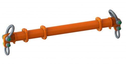
Modular Spreader Beam — 70 t, 1–14 m Span, up to 70 t WLL, EN 13155
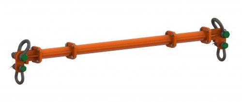
Modular Spreader Beam — 8 t, 0.5–4.5 m Span, up to 8 t WLL, EN 13155
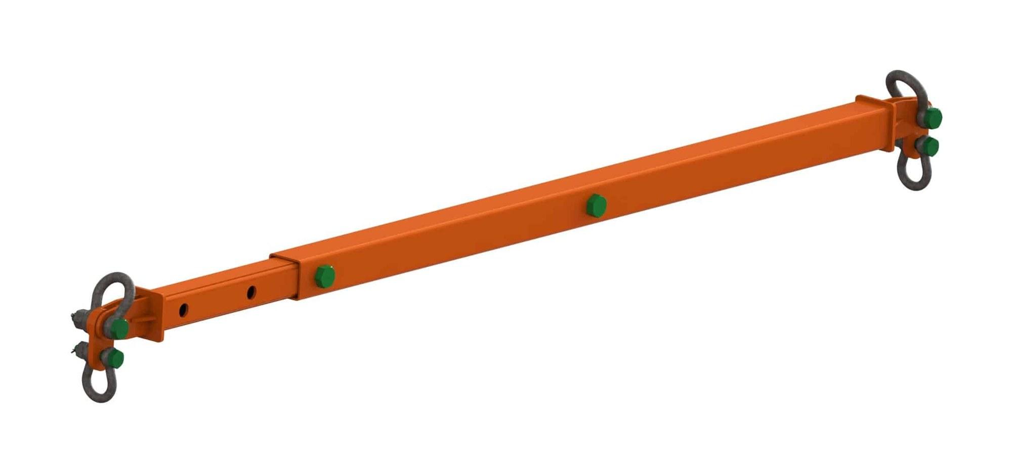
Telescopic Spreader Beams — 4 t to 16 t, EN 13155
Fixed & Custom Spreader Beams — EN 13155
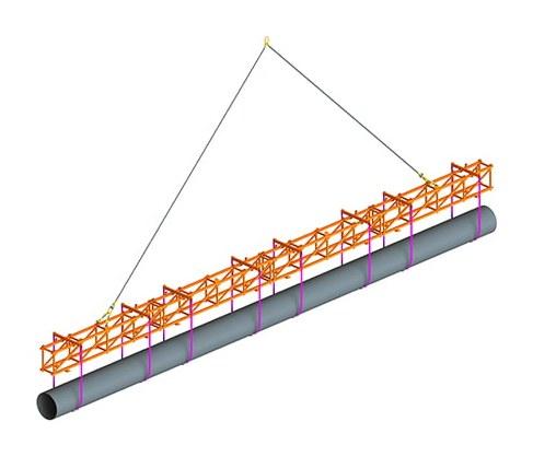
Lattice Spreader Beams — 3 t and 6 t, Loads to 44 m, 3 t WLL, EN 13155